31.8.18

Dome build: Top tier panels.


Wednesday: Drove to the builders' merchants for 3 sheets of 12mm birch ply but only available in 5'x5'. Went on making top tier panels. They are all the same base width but with different lengths and angles at the narrow ends.

Thursday: Very wet all day! Tidied the shed so I can have the miter saw ready and out of the rain. I fitted some large, heavy duty, shelf brackets to get stuff up and out of the way. The saw now sits happily underneath.

I realised the other day that my dome could be duplicated with much less effort in aluminium. Using square section for the ribs they need only to be V-notched precisely and bent to the closing angle. A dihedral plate will then be fixed over the inner side of the joint for the horizontal members to be attached.

The dome could then be covered in thin aluminium sheet. Hopefully a local engineer would guillotine the shapes to order from drawings or patterns. Each tier of panels would be identical to each other.

Pop riveting and/or gluing the covering to the skeleton will make the dome incredibly strong yet light. The panels could even be cut as a long tapering strip if there is enough guillotine capacity. They only need a gentle bend to be applied where they meet the joints.

Friday: Quite a pleasant day peaking at 65F.  I trimmed and fitted the first three 15mm birch top panels. They are so pale the dome now looks like a snow capped mountain. I haven't routed the underneath edges to lower their visible profile. They form the backbone of the dome where it joins the slit frame. I'll life with them for now to see if I'm feeling obsessive about it. I have a sheet of 12mm birch ply marked out for a lot more panels but need to confirm their lengths first. No point in wasting materials unnecessarily. I can use the previous panel to measure the edge length of the next.

It has been suggested that I undercut the lower edges of the top tier panels with the table saw. Which sounds like a far better way of doing it than routing. I can even set the saw blade over to achieve an angle to allow the boards to rest flat on top of the next lower tier.

Click on any image for an enlargement.

*

27.8.18

Dome build: Shutters.

*
It is blowing a gale and the rain has poured down. I have just had to go up and lash down the lightweight tarpaulins which had broken loose overnight. This exercise gave me a firm reminder of the power of the wind. Bi-parting shutters might easily become an embarrassment in our normally gusty conditions.

A typically curved, "up and over" shutter would not suit the faceted dome. It would need to be evenly curved to avoid complication. Flat, concertina panels, the height of the facets would be impossible without very tall channels to contain the ends. The hinges might leak like a sieve!

In the dim distant past some observatories had "cloth" shutters. Canvas or oilcloth would be the norm back then. A long strip of material, with cross sticks for maintaining smooth surfaces, would be hauled up and down via ropes. This would open and close off the observation slit. The "cross sticks" could be aluminium poles for lightness and stiffness.

Two ropes would be needed to maintain parallelism. A pulley each side, at the top, with eyelets inside the slit for the free ends of the rope. This would help to keep things tidy. A closed horizontal channel, each side of the slit, would keep the rain out. They would also hold the shutter close to the dome's angular surface in a gale. The whole thing would collapse into a concertina heap at the base of the slit when the ropes were let out. Distance between the cross sticks would only be one panel high. Or about 60cm or 2' in ye olde money.

Cosmetically it could be the most attractive option for my tiered and paneled dome. I'd probably choose a medium weight, PVC tarpaulin for long life and a suitable degree of stiffness. Though I'm not really sure how well it would cope with really cold conditions. It might become too stiff to self-fold easily. Though it would always be within reach to help it on its way down to the bottom. Presumably it would eventually take a set in its folds to ease the final descent. A box could be provided for the concertina to avoid it looking too untidy.

There should be considerable weight saving over any form of plywood, shutter construction. Less weight means it is easier to rotate the dome.

The image shows a mock-up of how a drop-down shutter might look.

Tuesday: I spent time sealing the edges of the covering panels. I found an easier way to cover the dome. I tie two large tarpaulins together by the eyelets and then drag the whole lot up to the top of the dome with a rope. It is then fairly easy to spread them out working through the top of the slit from the stepladders.

I have also started making heavier panels for the top of the dome using 15mm birch plywood. I want to get some strength into this space and struts weren't doing it. I have made three panels so far to go at the rear of the dome using a cardboard template.

For the corners and side panels I will need more material and think 12mm ply might be enough and certainly lighter. I brought out one of my longer Record wood planes to straighten the edges of the panels after using a jig saw to cut out the triangles.
 
Expert advice has put me completely off having a roll/fold down PVC shutter. I have decided that I'd go with traditional bi-parting doors. My original choice was to make them faceted like the dome. However, the sides of the shutters would need enough depth to be strong enough.

"Faceting" them would seriously cut into the depth of the side ribs. So it's a conventional rounded shutter look. I can always revisit the faceted idea if I find a way to do it well.  For the moment I just need a usable observatory. Preferably one which doesn't need to be covered every time it rains!

I had better get some materials for the shutters while I'm collecting more ply for the top panels. Unnecessary journeys with my trailer, the ten miles to the builders merchant and then  back again, is best avoided. Not least because of the time involved. 4'x8' sheets of ply would be better than 5'x5'. Cutting curved ribs is horribly wasteful of expensive materials. Though I can usually find another use for all the off-cuts. Precise cutting saves a lot of waste too.

Wednesday: Drove to the builders' merchants for 3 sheets of 12mm birch ply but only available in 5'x5'. Went on making top tier panels. They are all the same base width but with different lengths and angles at the narrow ends.

Thursday: Very wet all day! Tidied the shed so I can have the miter saw ready and out of the rain. I fitted some large, heavy duty, shelf brackets to get stuff up and out of the way. The saw now sits happily underneath.

I realised the other day that my dome could be duplicated with much less effort in aluminium. Using square section for the ribs they need only to be V-notched precisely and bent to the closing angle. A dihedral plate will then be fixed over the inner side of the joint for the horizontal members to be attached.

The dome could then be covered in thin aluminium sheet. Hopefully a local engineer would guillotine the shapes to order from drawings or patterns. Each tier of panels would be identical to each other. Pop riveting and/or gluing the covering to the skeleton will make the dome incredibly strong yet light. The panels could even be cut as a long tapering strip if there is enough guillotine capacity. They only need a gentle bend to be applied where they meet the joints.

Friday: Quite a pleasant day peaking at 65F.  I trimmed and fitted the first three 15mm birch top panels. They are so pale the dome now looks like a snow capped mountain. I haven't routed the underneath edges to lower their visible profile. They form the backbone of the dome where it joins the slit frame. I'll life with them for now to see if I'm feeling obsessive about it. I have a sheet of 12mm birch ply marked out for a lot more panels but need to confirm their lengths first.


Click on any image for an enlargement.

*

25.8.18

Dome build: Fitting the trapezoid covering panels.

*

Dare I start on the covering panels with the sky looking so threatening? There was light rain for about half an hour but I plodded on with the covering panels. Finished the bottom row by 16.30pm. It is finally beginning to take its proper shape again.

The skeleton had changed only a little on its long journey "upstairs." Just an 1/8" of an inch, here and there, where the pre-cut panels needed to be adjusted for position. Though I wasn't tempted to get the circular saw and sled out.

Perhaps I should have waited for the dome skeleton to stabilize. The base ring now rises and falls on the rollers as it goes around. I had to pack up some of the hold down disks because they were dragging on the base ring.

Later I realised that I could "let down" the base ring in the "high places" with some metal angle brackets. Though I'll see how it behaves first before making any hasty adjustments.

The sections not in contact with the support rollers will tend to more heavily load those which are. The roller have massive over-capacity so I'm not worried. I'm glad I went oversized and upwards in quality. This will hopefully provide long term satisfaction as my strength is lost with advancing age.


I just need to ensure the lift stop disks don't foul the base ring or the ribs. It was this which was causing the tight spot. There will be a tendency for the dome to climb uphill and roll down the other side. I had already noticed this. Sometimes the dome moves too easily when I lean on it accidentally. At others it needs a bit of a shove to get going. 

It is surprisingly difficult to spot errors in the base ring as it rotates. The eight steering wheels provide self centering. Which makes checking for eccentricity almost impossible. I can't watch all eight wheels simultaneously. So have to work my way around them while ducking under the stepladders.

The arches of my feet were hurting after days of working from ladders. I have now used nearly two whole cartridges of the Sikaflex 591 marine sealant. Though no great skill is required to run a small bead as an adhesive the "mastic" dispensing gun has proved adequate to the task. As I have one tube left I should finish the next two rows of panels with plenty of sealant to spare.

Then it is on to making thicker plywood panels for the top section between the dome and the observation slit framework. Now I have to drag myself back up there to cover the dome for the night.

Sunday: Cooler but sunny. First I finished the second row. Then almost the third row of panels by lunch time. Only a couple of panels wouldn't fit. So they will have to be trimmed using the sled on the table saw. Duly done. I messed up a lower panel with the adhesive when I tried to reach the top with a glued panel. I was doing quite well until then.

Monday: Pouring with rain and blowing a gale. I had to throw some ropes over the dome to keep the tarpaulins from flapping wildly. I couldn't tie them onto the skeleton because the panels have covered the struts. Flat sheets don't lie flat on a hemisphere. Which is why I chose a trapezoid dome.

These old, lightweight tarpaulins are leaking like a sieve in places! I have put down some storage tubs to catch the worst of it on the obs. floor. At least the DPC plastic seems to be shedding run-off outside the lower walls.

Click on any image for an enlargement.

*

23.8.18

Dome build: Gluing the gores together.

 *

Thursday: I started gluing the gores together. Because each gore has two sides [ribs] I only need to glue every other one. Then, when that gore is carefully pushed back in, it glues the ribs on either side. Once glued, working from the outside ladder with a mastic [caulk] gun, I go back down. Then climb back up inside to the dome. Here I turn the glued gores to the south so I can fit the 20 bolts, washers and nuts through the pre-drilled holes in the ribs.

I face out from the internal stepladders and climb steadily as each bolt is inserted. Then I use a rechargeable drill with a Torx bit which fits the hex socket heads. This quickly tightens all the bolts as I apply a spanner [wrench] to the nuts.

After that I still have to glue the base strut of the gore to the dome's base ring using a flat crowbar to lift them. Then tap the long csk screws up from underneath and apply a washer and a nut to each. Cranking on the nuts with a spanner tightens down the base strut onto the glue-sealer.

It keeps getting dark as if it might rain. Though none is forecast until late this evening. I have a lot of tools out and the bare dome skeleton doesn't want to get wet either. I have stopped for a rest at 17.30 as I am very tired and aching all over. I have five sets of ribs competed and two more to do for 14 in total. The observation slit counts as two more.

The safety harness was an uncomfortable nuisance. So I made an old fashioned, climber's rope belt from three turns of thicker rope around my waist. A caribener is then hooked over the triple strand belt and onto the loop to my scaffolder's hook. No point in taking any chances of a fall when I am tired and concentrating on the work.

After tidying up I had to cover the dome with two large tarpaulins for the overnight rain which carried a cloud burst warning. The problem is that the dome won't turn with a lot of cords tying the covers down. It makes it too time consuming to try and finish the last pair of gores between showers. 

Friday: Blowing quite hard with showers forecast. It might brighten later. The covers stay on until then. In the afternoon I did manage to glue another pair of ribs and bolt it all together between hefty showers. I'm trying thin work gloves to save my hands being covered in black sealant. Had I known that only black was available locally I would have bought it online. I'm not a messy worker but the ladder sometimes gets in the way of the push rod of the mastic gun.

The gloves makes it more difficult to thread the many nuts on with my left hand. Being faddy I wanted them all facing the same way. Using the drill to drive the bolts tight saves so much time it is worth having them all right handed. My left hand feels as if it is sprained when I use it. Though I don't remember injuring it. I couldn't hold the drill with that hand.

Eventually I had to retreat indoors when it started thundering quite close-by while I was up at the top of the 20 foot aluminium ladder! I just manged to cover the dome as the rain started tipping down again. One more gore to do and I can start covering the dome with the pre-cut plywood panels. Will they still fit?

Saturday: Finished the last gore gluing. That's used up 140 bolts, 280 washers and 140 nuts. Added another 14 bolts to hold the base of the gores onto the base ring. There were already 28 in place.

Then I spent some time adjusting the steering wheels. The lock nuts on several axle bolts had come loose. I had to rout some rib notches deeper to clear the hold down disks. The dome turned more freely after that. It had one tight spot so I went round and round checking wheels for freedom without finding anything amiss. The promised thundery showers held off apart from a few spots of rain just before lunch.

Click on any image for an enlargement.

*

20.8.18

Trapdoor/hatch revisited.

*

The problem with climbing a ladder through the pyramidal pier is the lack of shoulder clearance. It is perfectly adequate until something projects into the space available. That projection would be the vital support for the free end of the hatch. I have racked my brains for ages trying to overcome this problem. Until today, when it suddenly dawned on me. 

I could have hinged toggles, one either side. These toggles would lift effortlessly out of the way if my shoulder struck one, or both, on the climb. The toggles would be smooth and well rounded to avoid impact or corner penetration injuries. They also needed to be lightweight to avoid inertial mass preventing free lifting on impact. This last requirement excluded heavy sections of aluminium.
The ideal material proved to be 3/4" Baltic birch ply. Offering adequate strength without unnecessary weight. The toggles would be made overlong so that the tail ends were stopped against the underside of the floor. A sturdy block would be placed directly under each toggle support area. So that the pivots were relieved of almost all of the downward loading. The trapdoor plus my own full weight must be safely supported without any risk of failure.

The pivots will be 8mm ss bolts with plain shanks passing through a 7.5mm hole through the 2x6 joists. The toggles must drop freely by gravity alone to provide absolutely fail-safe support. The toggle stop blocks are bolted through the supporting joists.

A micro-switch and battery driven, red LEDs will provide a clear indicator when the hatch is open.

Wednesday: Fixed the hinges of the hatch and trimmed the planking. After removing the tarpaulins I had a disaster in the afternoon when the slit frame fell sideways inside the dome. I had removed the bottom plank for routing. While using a block and tackle to pull the base back in the short rib extensions at the top of the dome cracked off. Allowing the frame to drop sideways.

I tried lifting it manually but it was well in excess of my strength. So I set up a 2x4 as a gin pole and was able to tip the frame back upright with judicial rotation of the dome. Thankfully it has remained in place overnight. It would be difficult to prop up the frame without losing the ability to rotate the dome. Which I need, to be able to bring each gore, in turn, to the 6m, 20' ladder for gluing.

Click on any image for an enlargement.

*

19.8.18

Observatory Paint Job:

*

Saturday: Windy but bright so I am painting the observatory walls with the mineral treatment. The grooved plywood darkened quite quickly. Which nicely took the edge off the rather bright panels. It will darken further on exposure to sunshine. I half finished the entire building exterior before it rained. 

Sunday: Still painting. It is much faster to use a larger brush than the skinny 2" I started with. Though the 4" uses up a lot more of the liquid. 

This stuff is quite unlike any normal paint. 5 grams of magic powder per liter of tap water doesn't thicken the water at all. There is also a slight delay before the wood darkens. It comes in a small paper packet of 25g for making 5 liters. I found it on eBay[UK] after seeing it mentioned on a YouTube gardening video. It is widely available under different trade names.

The treatment is supposed to resist fungus growth by affecting the natural metal salts in the wood. Chelating is mentioned in the literature. I like the naturally weathered look. It is claimed to be perfectly safe for children's wooden toys and organic vegetable boxes. I must admit to having splashed myself repeatedly without any ill effects. It does not stain the skin. Wasps chew right through the "earthen" finish when collecting wood pulp for their nests.

Because the mixture is so thin there are terrifying purple grey splashes and runs below the area being painted. It feels as if each board has to be completed before daring to start on the next. Though there really is no need to worry about any marks remaining. Once the splashes and wet wedges are painted over everything vanishes intro the uniform grey-brown.

It seems  too obvious to mention that care should be taken not to splash nor drip the muddy fluid onto any wood which you do not want to be treated. It will instantly stain it! So be warned.

Rather than worry about wet edges and splashes I found I could start at the top and work right across a 4x8 cladding board from a stepladder. Followed by the lower sections while sitting comfortably on a beer crate. This saved me from kneeling or crouching on the rough gravel.

By lunchtime I had painted the entire ground floor outside walls. That just leaves the upstairs observatory walls at the rear to do. The stained effect is  more subtle in today's overcast. The bare wood looking far more orange in sunshine. The colour changes to darker and a more even earthy brown over time.

The plywood cladding boards are made by Selex in 9 & 12mm thickness with a lap joint on the long edges only. I chose to use 12mm for extra "stressed skin" strength to stiffen up the octagonal building.

It is claimed to be Radiata Pine and is almost completely free of knots and cosmetic faults on the face. However, the internal plies are of inferior material and most boards have dark and rough knots showing in the bottoms of the machined grooves.

These Selex boards sell at discount DIYs chains for about 1/2 to 2/3rds the price of those available at regular timber merchants. Ironically, the latter's products are often infested with surface knots all over the face veneers.

Presumably all of these boards are intended to be painted rather than clear stained. Nor are the rear faces intended to be seen as they are often covered in ugly knots. They are popular for carport cladding and the gable ends of buildings. I clad my shed in these grooved boards and it has survived for years without ever being painted.

Arranging a short ladder to bridge between the obs. and the shed roof allowed me to reach the obs. wall panel on that side. The outside painting is finished. I removed the fencing on the shed sides ready for clipping to length with bolt croppers. I had left these panels long in case I decided to use the remaining fence panel.

The fence posts are not available separately. That would have allowed me to join the fence panels to the obs. wall on the shed side. Which would have been a bit tidier. I have been using fencing staples because this area is almost invisible form the ground. The reinforcing to the veranda walkway joists was well worth doing. It feels very firm now instead of springy in places.

Later I took down the white tarpaulin and put  up a couple of smaller green ones in its place. Certainly much less obvious from any distance. It was difficult and time consuming to arrange the tarpaulins in the wind. They kept lifting and sliding off sideways! I still need to slide a smaller green tarpaulin under the slit side for tonight's promised rain. Job done.

Click on any image for an enlargement.
*

16.8.18

New trapdoor hatch in larch.

*

With the realization that I could counterbalance even a heavy hatch I have built a new hatch in larch board. Last time I side hinged the hatch and this was far too clumsy because of the handrails. The leverage was all wrong because of the narrower hatch width. Hopefully a longer lever, from an end hinged hatch, will be easier to handle.

This time I pushed the hinge line well forwards beyond the stepladder's top rung. The outer edges, which fall within the pyramidal pier, will need to be tapered to clear the 4x4s. So I chopped these corners off neatly with the miter saw.

I shall add a toe bumper to the pier end of the hatch. Just in case my feet should accidentally seek out the gap beyond the hatch inside the pier. Very unlikely but it costs practically nothing to fit one. It is just possible that I might slip on the hatch while moving towards the pier. Perhaps if I was coming in from the veranda with snow on my shoes. The bumper should prevent any sudden "rabbit hole" moments. 

The hatch overlaps the pier footprint by several inches. So it should be difficult to find fresh air beneath my feet even in the dark. It is unlikely I'd be standing right next to the pier while using the telescope except while viewing overhead towards the east.

The images show the results of my labours without the hinges being bolted into place. I still need to recess the hinge areas so that they can lie flush. The hatch is much easier to lift from below thanks to the improved leverage. This is despite it being longer and heavier than the last. It was more difficult to struggle up the steps but much easier to work with it once in place.

I shall still have some counterbalancing but wonder whether cables are really necessary. The loads are quite paltry for almost any diameter of stranded steel cable. I can measure the counter-pull required with a spring balance. Then halve the measurement for a weight, cable supported from each side. This will avoid twisting forces on the hatch.

Once I have the hatch hinged properly I can replace the narrower boards each side of the hole in the floor to fill in the gaps.

Friday: More stainless steel bolts and nuts arrived so I could replace the already rusting black bolts for the steering wheel axles. These had plain shanks so were a much better fit for the steering wheels and disks.


Click on any image for an enlargement.

*

15.8.18

Dome build: A new trapdoor design:

 *

Tuesday: I covered the dome with an old, white, lightweight tarpaulin so I could work with power tools if it rained. Notching the ribs was done with a cheap, Chinese router working freehand. The tarpaulin gives an idea of how the dome would appear in white. The neighbour's trees and hedges have grown considerably since I last worried about dome colour.

Wednesday: The tarpaulin is doing quite a good job except where it is too short across one diameter. At least the observatory floor stayed dry. I keep rotating the dome to match the wind direction to keep the rain out.

I have been looking at the trapdoor again and fiddling with the ladder height with blocks. I need the top tread level with the rest of the floor for safety. I also need a level surface beyond the top tread for my overhanging toes.

Deciding on the hinge line is the main problem. It obviously has to be well beyond the ladder top or the trapdoor will stop natural footfall as I reach the top tread. My latest idea is a plate of aluminium to lie flat on the top ladder tread. This will be hinged about 8" forwards of the ladder top. Since the trapdoor will be normally closed the plate will only lie in the gap between the ladder handrails. It will not be used as part of the normal floor except when looking directly east. I could get some adhesive grip tape to avoid any slipperiness when standing on the metal plate. It will on the route to the veranda via double doors.

Sturdy T-strap hinges are an alternative to separate hinges and a metal plate. The hatch will be supported on  metal dowels projecting from each of the floor joists for even support. I have to be careful that the dowels are domed to void injury while climbing the ladder.

The new trapdoor will probably be a plywood sandwich. Using 1/2" grooved boards top and bottom. This will help to simulate the rest of the larch flooring and to provide some grip. Unfortunately the larch boards proved to be massively heavy. I had made a larch trapdoor ages ago but could hardly lift it up as I reached the top of the ladder. So I have done without a trapdoor ever since.

Stepping repeatedly over the large hole in the observatory floor has taught me to respect the not inconsiderable risk. I looked at boot scraper style doormats as a ventilated hatch option but they were also far too heavy.

Counterbalancing a heavy trapdoor is not an easy task when the mechanism must not impede movement around the telescope in the dark. Cables most not cross walkways nor risk any chance of tripping the user during normal use. There must be no crossing levers which could remove digits in the dark. Fool-proofing under all circumstances is absolutely vital.

I have just realised that cable pulleys could be attached to the stepladder handrail extensions. This would keep the cables well out of the way of normal movement within the observatory.  See the image left where I have lifted the boards beyond the ladder top for measuring. The hatch opening is on the right.

The weight cables need only small holes to run through vertically below the far side of the pulleys. The weights would fall near the floor, inside the west wall of the octagon. Where they can do no harm if a cable joint gives way. This area is below the stepladder so is not a normal thoroughfare.

The leverage applied by the cables changes with the angle of lift. Lift is modest as the trapdoor starts to rise. Is at a maximum at the halfway point and then declines as the trapdoor moves between the handrails. This is an ideal situation during normal hatch lifting. The trapdoor stays safely in the horizontal position. Except when it needs to open.

While counterbalancing could aid in parking the trapdoor in the open position this must not resist easy closing. Now I need to find a way to effortlessly close the hatch once I have safely gained the observatory floor after climbing the stepladder. The answer to easy closing may be simply to make the weights too light to hold the hatch open once it is past the [vertical] tipping point. Once started on its descent it would drop automatically.

I have lots of barbel weights to finely adjust the counterbalancing. A knotted rope could hang down below the hatch when I want to pull it closed from below while descending the ladder.

Gas struts, as for car boots and hatches, are an alternative lift-lower device but unlikely to provide the long term, ease of movement of cables and weights.


Click on any image for an enlargement.

*

13.8.18

Dome build: Lift stop disks.

*

Having finally decided on round, storm lift stops, I sawed out  seven more, 10cm squares and then cut off the corners. Then I stacked them onto a length of M8 studding in the lathe. Turning octagons into circles is a noisy business. I used the lathe drive and small cuts which is time consuming on thick aluminium. The end of the temporary axle was drilled with a center drill and then supported on a running center in the tail stock.

When it came to fitting the disks to the steering wheel axles I quickly discovered I had no spare M8 nuts. It required at least three nuts per axle plus the Nyloc nut on the bottom. My stock of longer M8 bolts was also rather limited. I needed something much longer than the existing stainless steel hex-socket heads. My lifetime collection of old coffee jars of fixings produced some black hex-socket head screws. These are bound to rust but at least I could assemble the disks to see how they performed. 

Then rain stopped play. So I retreated back indoors for lunch. I still need to notch the base of the ribs to clear the disks as the dome rotates. I also need to modify the 2x8 plank at the base of the observation slit. The disks obviously can't pass through solid wood! The board needs to be slotted to an inner radius. Or raised off the base ring with a larger radius arc of solid spacer material. Leaving an inner track clear of the lift stop disks. 

The images above show the sequence of steps required to cut eight 4" Ø disks out of scrap, 10mm, aluminium plate. The final result needs new stainless steel fixings. Longer screws with nuts as spacers will protect the skateboard wheel bearings from end loads. I had to use stacks of washers as spacers and this is not a stable solution as well as risking overloading the bearings.

Tomorrow's weather is another cloudburst warning from the DMI so I had better make what progress I can today despite today's light rain.


Click on any image for an enlargement.

*

9.8.18

Dome build: Bolts and dome retention.

 *

Wednesday: The bolts dispatch is finally notified just as we have a 15 minute, torrential cloudburst.

The following is a wordy example of my thought process in arriving at my original lift stop disks. Feel free to skip over it:

Thursday: The M6 x 90mm hex csk head bolts arrived late morning. I then started drilling down through the original wood screw holes with a 6mm bit. By working from the outside of the octagon I could reach the drilled holes in the base ring from the underside with a countersink in the rechargeable drill. The bolts were then pushed upwards from below, an oversized washer slipped over and finally a nut. The 12mm Ø CSK heads were then pulled below the surface of the dome rotation track. Cranking on a small ratchet driver with a 10mm socket then pulled the horizontal struts and base ring tightly together.

The forecast, for this evening and tomorrow, is for extended and heavy, thundery rain and high winds. The open dome skeleton is presently in little danger from the wind but is bound to get rather wet. Gluing and sealing of the gores and covering panels will now have to be timed depending on the weather.
This total change in previously stable, hot and dry, weather conditions is requiring a rapid rethink of safety factors should the dome covering panels go on. The dome then becomes subject to wind loads and possibly lift. Particularly before the shutters close off the still wide-open observation slit of the dome. Perhaps I should have the shutters ready first?

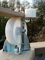
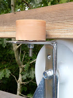
I had better start fitting lift restraints on top the steering wheel bolts. These plates need be no more than rectangles of thick [10mm?]  aluminium with a hole in each for the steering wheels, axle bolts. The plates will skim just above the base ring as the dome is rotated. So that each becomes a solid lift stop in the unlikely event of any aerodynamic lift during gales or stormy gusts.

An alternative would be cut circles of aluminium to fit on top of the steering wheels and [perhaps] rotate with them. A small spacer will ensure the upper wheel bearings are lightly pre-loaded. Since I have eight to make it might be worth using a large hole saw and finishing off the disks in the lathe. I'll have to check the required diameter. I don't have any alu. round bar stock of sufficient size. Besides parting off disks of the likely diameter in the lathe takes far too long.

I don't remember any commercial disks, or suitable wheels, which would suit as donor material. These disks need to be smooth as they will literally protrude into the observatory. Anything sharp edged might cause serious injury in the dark as they are exactly at head height. Which is why I am seriously considering disks rather than rectangles or squares. They need to be thin, stiff, long lasting and strong. I can easily 'soften' the sharp edges of metal disks in the lathe.

The dome retention plates obviously need to be larger than the steering wheels so that they overlap the base ring. About 90-100mm Ø would do. The ribs would have to be notched at their base to let the disks pass through them. The plywood base ring is not perfectly round and the dome 'wanders' slightly during rotation. So there is no point in trying to use undersized disks.

I shall have to modify the skateboard wheels by cutting away the downward facing 'cupped' side to lower their top surface. This will allow me to remove the present packing nuts. Which had to be inserted in the depth of the wheel "cup" to clear the shelf brackets. Removing 7mm of wheel height was enough.

Best achieved by holding a hacksaw very firmly in contact with the spinning wheel in the lathe. Followed by a clean up cut. I tried water and soapy water as cutting fluids but they didn't help. The experts freeze their wheels before attacking them with a lathe.
Other dome builders have fitted parking lift restraints or hooks. Which are set [and sometimes tensioned] only when the dome is not actively in use. I may add these types of restraints later as extra insurance for storms. Though I hope the multiple plates or disks [all 8 of them] will be adequate by themselves for more normal, but windy weather.

Friday: I went up to the observatory as the tail end of a storm still buffeted the woodwork. Inserting my finger into a deliberate gap between the pyramidal pier and the observatory floor suggested only microscopic relative movement. The mounting pier is, of course, fully isolated from the observatory structure. This is to ensure footfalls [and the wind] don't cause vibration in the highly magnified, telescope image. The pier is sheltered from the wind by the building.

Narrowing the skateboard steering wheels was completed one at a time. Then each one replaced on the dome support ring. Removal of them all at once was considered too risky in the very windy conditions. Online searches [on eBay] for pre-cut disks in aluminium or stainless steel showed they are ridiculously uneconomical. I shall have to make my own disks from scrap, sheet aluminium. It is just  a matter of how best to do it in the minimum of time.

Cutting squares [or rectangles] is easy enough on the miter saw. Drilling and bolting each in turn will provide a means of support in the lathe. It would be better if the corners could be removed first to ease the impact loads when turning them round. The miter saw is not the ideal tool for trimming of small items. Perhaps the jig saw is the answer? Unfortunately, the 8mm bolt diameter is really not ideal for stacking several disks at a time. The disks cannot rotate with the wheels anyway.

Perhaps I should rethink the disks idea and return to squares. Or completely separate the steering wheels from the means of vertical dome retention? I looked at this option and realised it would be visually clumsy.

Squares with well rounded corners, for safety, will do. They would be stronger than disks and less able to become unhooked by simultaneous lateral and vertical loads. Rectangles it is then. I chopped them out from 15cm wide scrap 10mm thick aluminium on the miter saw and then quickly smoothed the edges and corners with the 12" disk sander. I used lamp oil as a cutting medium on the saw but still had blocked teeth on each cut. The problem now is deciding on the best amount of base ring overhang.

Later, I realised that square lift stops would rotate if the corners dug into the dome structure. Which would lock the dome against further rotation. The radius to the corners is far greater than the radius to the sides. So it's back to disks and I have one finished and more ready to turn in the lathe. The miter saw can cope with the small squares by clamping them down onto the bed with  Bessey F-clamp and lowering the saw very slowly. This allowed me to take all the corners off. Which saved a lot of time.

Click on any image for an enlargement.
*

5.8.18

Observatory build: Boarding and DPC flashing.

*

Thursday: Screwed 12mm plywood pads to the tops of the obs. walls to support 5" larch boards. It feels very warm working in the sunshine @ 80F. It has helped to keep the power saws in the shade of the tent awning. So I can escape from the relentless heat and blinding sunshine now and then. Three larch boards were duly mitered and fitted. Which, I thought, made the obs. walls look much more finished.

I used my old Record 043 plough plane to cut a water drip under the octagon's, dome support ring. It would have been far easier to have sawn a slot before its final assembly. Too late now.

A few planets have been dragging their heels along the horizon. They are so low that I have to go upstairs to look down at them through intervening trees and hedges.

Friday: 82F. Fitted the rear three boards under the octagon's top ring. I'll have to make up a short roof ladder for the shed roof. So I can work on the otherwise inaccessible side of the octagon in safety. I have two pairs of ladder ridge hooks hiding in the shed somewhere. They were handy for allowing me to sweep my own chimney each year.

Once the worst of the heat was gone I used the roof ladder to finish the board on the seventh side.

Sunday: 72F. Removed top boards and ply panels again to fit plastic DPC flashing to the base of the obs. walls. This is to ensure that most of the dome/obs. run-off falls safely outside the lower octagon walls. As it neared 1.30 the sky went dark and we were teased by a few spots of rain. Having quickly tidied all the tools away it immediately became sunny again.

I find myself rehearsing possible methods for sealing the gores together in the middle of the night. The rehearsals, I meant, not the real thing. I'm still waiting for the 90mm bolts for the bottoms struts to base ring. So can't make a start. No stock, it seems, though I could easily have been informed a week ago.

I spent time over the last couple of days fixing short joists to support cantilevered floor boards on the veranda. There was no real danger but springy floor boards don't fill one with confidence. They can also distract the user with a potential risk of collisions with the scenery. When they should ideally be relaxed and looking where they are going.

The protective "fence" is easily high enough to contain the unwary and will eventually be raised slightly to lift the metalwork clear of the veranda floor. Any puddling on the veranda could eventually eat into the galvanized metal. The support posts can soon be cut off to length. Then these uprights bolted to the wooden structure for even greater stiffness and strength.


Click on any image for an enlargement.
*