*
Tuesday 30th 39-41F. Gales and light showers.
The new, miter saw blade has arrived. With 100 of the usual hard point teeth it is intended for aluminium and other soft metals and materials. I had a nice discount because of Black Friday Sales.
*
*
Tuesday 30th 39-41F. Gales and light showers.
The new, miter saw blade has arrived. With 100 of the usual hard point teeth it is intended for aluminium and other soft metals and materials. I had a nice discount because of Black Friday Sales.
*
*
Sunday 28th 36F, cool, misty with misty rain.
I have ordered a new, discounted, aluminum cutting blade for my 12" DeWalt, miter saw. It is the only way to sensibly manage the 120mm square tube.
I will need to cut even larger, aluminum, box tubing for the new, cross axis mounting. Up to 4"x8" sections are waiting in my neatly stacked, scrap pile. There is no way to cut these absolutely square without wasting countless hours on truing up skewed cuts.
Which was what I did with the last mounting. Lots of 10mm plate was cut with a Bosch jigsaw and lamp oil. The Bosch wouldn't know a straight line if it met one. Sanding edges square on aluminium is an exercise in frustration. It takes forever and the sanding material clogs almost immediately. I even bought some carbide disks for the angle grinder but the coarse grains loaded up to useless in no time.
*
*
The box section tube turned out to be 120x120x5mm. Which is fine. I marked up a 49cm length. It will be parted length-ways after cut-off. I only managed to square one end with the jigsaw and a new, fine tooth, metal cutting blade. It was slow work despite trying lubrication. The teeth of the blade soon loaded up while using light oil. So I dug out the lamp oil ready for the next step.
A coarser toothed, aluminium blade would be better. The fine teeth and short blades are probably intended for mild steel. They clog too easily in the softer metal. I could use the miter saw but it makes a hell of a mess! The blade is also much thicker. Which wastes material unnecessarily. An ordinary hacksaw is so slow in 5mm wall thickness aluminium that it would be foolish to even try. A slow turning, cut-off saw would be ideal but economically unrealistic.
Rain in the afternoon stopped play.
*
*
Thursday 25th 42F. Rainy start. Still very dark at 08.00.
Yesterday I spent some time fiddling with the new skate wheels on the right shutter. I kept adding spacers to make the shutter concentric with the dome. A couple of 10mm nuts outside the wheels was all it took. The problem was an increase in cantilevering of the wheels on the extended axles.
Properly supporting the wheels has become the latest hurdle to overcome. Do I need a channel of some kind to reach over the wheel without being too bulky? I looked at using brackets from the ribs at the side but the geometry is all wrong. Everything I add has to, quite literally, pass through the slit ribs. Which means cutting more rib away.
I could make a much more sturdy axle with the 8mm bolt as an extension. Then all I have to do is fix the axle immovably to the shutter. No idea how that would happen.

A third wheel in the center of the shutter would help reduce the cantilevered and local loads on the other two. Four wheels even more so. I have eight!
I quite favour this idea. Though it needs the shutter, bottom boards to be beefed up and properly fixed. Or completely replaced. I am presently using off-cuts from 2x4 softwood. Not ideal as the wood can't resist localized loading from the foolishly extended axles.
The angle profile, wheel support could be bracketed directly to the shutter ribs. I still need to bridge the curved [highly asymmetric] gap to the GRP shutter covers.
Up to this point I haven't fixed the covers to the bottom boards. Relying instead on the multitude of brackets fixing the covers to the shutter ribs. The softwood bottom boards were only temporary to see how things progressed. They were only put there to hold the drawer slides. Which have proved to be completely inadequate.
If I can find aluminium angle profile wide enough I can shape it to reach out to the GRP covers. Then I can bracket to the covers as well as the ribs. Allowing the use of the matching 10mm bolts where they are visible on the outside of the shutters. Which way up for the angle profiles? They could have the open side up. To allow easy access to the axle bolts. This is all beginning to take proper shape.
Now I just have to find two, sturdy, angle profiles nearly 60cm long. It looks as I shall have to cut up some of my [scrap] 5"x5" aluminium, box section tube with 5mm wall thickness. To make two, very wide, angle profiles. I was saving this material for the cross-axis mounting. If I can't complete the dome I won't need a new mounting!
*
*

10.00 Optics dewed again. Though it wasn't so cold last night. 39F. I removed and dried the D-ERF with the hair drier. Remembering to shield the objective from direct sunlight. The I turned the telescope away from the sun while I warmed the objective. Both dew bands on full. The D-ERF blocks the sun's warmth to the objective which might otherwise help to clear the dew.
10.30 Thin cloud obscuring the sun. Making the sky white. Using the 1.6x GPC for wider field of view for the large, southerly filament. Far too much gain needed even at 10m/s exposure. [200] No useful image so far.
Now my neighbour's tree is rocking over the image! I have set the telescope almost vertical to warm in the sunshine. I can feel warmth on the woodwork in the dome. So there is some solar heat to be gained. With the objective at the top I'm hoping for some chimney effect.
I kept capturing new videos but the images were spoilt by the thickening cloud from the NW.

13.00 I have fitted two larger skate wheels to the right shutter. It rolls far better but the wheels need much better support and from both sides. The wheels are leaning over with the long, cantilevered bolt into the bottom board.
Being so "grippy" the rubber is dragging as it rubs against the channel. I thought I was missing something obvious but the "top hat" spacers were for 6mm screws. I am using 8mm bolts which match the bearings. I am wondering if I can use large metal or plastic spacers to keep the wheels upright.
I had to trim the slit ribs to allow the larger wheels to pass. Then trim the bottoms of the shutter ribs so they didn't drag on the channel. The bottoms of the shutters need to be lifted, pushed outwards, or both. They aren't concentric with the dome. The gap is smaller at the top of the original door height.
13.05. Full overcast has arrived. Time for lunch.
Heavier cloud in the afternoon with a shower at 16.00.
*
*
 Monday 22nd 31-41F. White frost. Early cloud clearing to bright sunshine. I have my Kamik winter boots and winter clothes on.
 I have ordered a new set of bigger wheels for the shutter slides. 84mm Ø in the cheapest inline skate wheels I could find. In a set of eight including bearings. These should provide plenty of axle clearance over the aluminium, channel walls.
I also ordered more 60mm Ø skateboard wheels to match the steering rollers on the plywood dome. The number of rollers on the bigger dome rises to 14 from the previous 8. Hopefully the increased number of steering rollers will help to maintain concentricity of the larger dome on the bigger building. See the image of the rotation and steering roller combination. Including aluminium security disk against lifting.
As usual, after a cool night, the optics were dewed. I put both heat bands on full without effect. I have now wrapped the forward section of the main tube, behind the objective, with layers of closed cell foam for insulation. Leaving the last few cm bare to hold the heat band.

14.20 Image of large southern filament shows the dew has cleared. The the bare sections of the main tube felt luke warm to the touch after an hour.
Now the sun is dragging itself along the ridge of the house. Mushy and wobbling image on the monitor. I am unlikely to get a better image than the first after lunch. I didn't. Another hour wasted.
*
*
Sunday 21st, sunshine promised but very cloudy. Coming from the west then north west.
I trimmed the ribs to provide clearance from the skate wheels and base ring. Skate wheel axles still dragging on the channel. I haven't reached the shops to buy a plastic filler strip yet.
Or, I could buy some larger inline, skate wheels. Those I have now are 72mm and cost small change secondhand. While 84mm would give me 6mm increase in radius. Ensuring plenty of axle clearance over the channel walls. 80mm is an option but that would be only 4mm clearance. Which might be too tight. Ironically, a couple of strips of 30mm x 5mm plastic from the DIY store would cost the same as 4 wheels including cheap bearings.
10.00 Tried imaging but very cloudy. Optics dewed. Particularly the objective. Have 2 heat bands running flat out. [90F.] Repeated blasts with the hair drier. No obvious change so far.
Two widely spaced, small sunspots. A large, S-shaped filament in the south. Soft and useless images as it approaches 12.00. Becoming even cloudier. Still dewed. Giving up.
Showers in the afternoon.
*
*

I made very little progress yesterday. The inner shutter ribs are obstructed by the base ring. If I cut away the ring I lose its strength.
If I cut away the shutter ribs they could end up at half mast. If they remain as is the shutters wont close without being lifted bodily. Which throws the support off center. Leading to laterally leaning shutters.

The shutter ribs are resting on the channel and base ring. Rather than the wheels. Which makes far too much friction. I still need to get to the shops to buy some plastic strip to place in the channel. This is to raise the axles clear of the channel.
*
*
Friday 19th 53F. Another grey day with a heavy overcast.
I notched the bottoms of the slit ribs to allow the skate wheels to pass unhindered along the channel. The shutter, bottom boards were freed from their brackets. This allowed them to be raised to a better position.
I may leave the top drawer slides in place. Relying on the robustness of the lower tracks to achieve better alignment. There is very little room up there for the channel and skate wheels to fit between the boards.
*
*
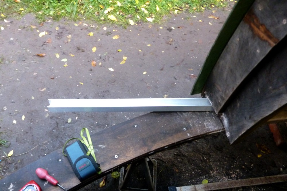
Yesterday afternoon I notched the ribs enough to be able to thread the channel rail into position. The extension beyond the base ring can be seen in the first image. Not too extreme. The rail is cut rather long. To avoid it being too short if I need to add support beyond the run of the skate wheels.

It has occurred to me that the individual top drawer slides may not be parallel. The screws have started pulling out. A single, channel, top rail will guarantee they are both straight. Though not necessarily parallel to the lower rail unless I make it so.
There is also the matter of the height of the tops of the shutters when converted to wheels and channel. Will this change the height of the lower shutters? Perhaps I should concentrate on the upper rail first? I have to introduce the wheels between the shutter top boards and the dome zenith board. This is bound to affect the lower shutters. It might be risky to expose the shutter wheels to the weather on the outside in the long term. So it is arguably safer to have them positioned internally. Shame it is raining again!
*
*

Image shows the new top track resting on top of the dome. It cannot go any lower without cutting into the dome. Photographed at dusk. The pipe insulation continues to work well in protecting the dome from abrasion by the ladders.
Having converted to channel profile tracks raises a number of issues down at the bottom. Channel positioning is both optional and critical. With many positives and negatives arising from different choices.
I plan to have the skate wheels inboard of the shutters' timber, bottom boards. The wheels and tracks are three times the thickness of the [soon to be discarded] drawer slides.
Outboard: The further away the lower channel rests, from the center of the dome, the more exposed it is to the weather. Channel support from the base ring reduces with greatly increased cantilevering at the ends. Sturdy support will have to be found from beneath the base ring to support the heavy shutters. Leading to potential conflicts during rotation.
Inboard: Bringing the channel inboard, nearer the dome means I have to avoid the inner edge of the base ring. Otherwise my storm anti-lift restraints become blocked. Which would prevent the dome from rotating. I do not favour manually operated latches. It is far too easy to forget them. So I have permanent latches always at the ready in case of storm. I used heavy aluminium disks in the case of the plywood dome. These have worked effortlessly for several years.
A more inward, channel position, provides much more support from the base ring. With considerably shorter overhangs beyond the outside of the base ring. Leading to improved cosmetic appearance. Which are all major positives IMO.
The bottoms of the slit ribs will have to be heavily notched. To clear both the fixed channel and the 72mm Ø moving skate wheels within the track. 75mm + clearance above the base ring. Making oversized notches in the wrong place would be a nuisance. Weaken the rib junction with the base ring and probably end up looking horribly untidy.
The problem is that the slit ribs have to be notched somewhere. To allow me to play with different channel positions. There is presently no room to slide the channel under the bottoms of the slit ribs. So I have chain drilled suitable notches and will use the DeWalt multi-tool to saw out the notches.
Despite the high cost of DeWalt saw blades the latter is proving poor at plunge cuts into Baltic Birch ply. I upgraded to a Titanium coated blade. It soon wore out with only very occasional use. The "ordinary" quality DW saw blades soon wear their teeth down to a smooth stump. Not what I'd call a professional quality tool at all. Though the vibrating multi-tool does have unique advantages. Particularly where no other saw can be brought to bear in a tight corner. The sanding qualities with the small, Velcro attached, abrasive pads are quite pathetic.
*
*

Yesterday, while I was trying to raise the shutters one of the upper drawer slides began to lose its fixing screws. They were quite literally tearing out of the plywood shutter board. It is obvious that I need a much more robust, replacement roller system.
The image shows that the vertical and horizontal spacing of the shutter slides. This large spacing has no effect on the loads on each slide. Each must bear half the total weight of each shutter.

I don't believe it! There is another scrap yard in a quiet country lane which is rarely open. He has a stack of clean, aluminium U-profile in very long lengths! Absolutely perfect for my needs.

The wall height of the channel, U-profile, rubs slightly on the 8mm axle diameter. Though, despite this, the wheels happily rocket down the channel on an incline. I may have to sand the walls down slightly with a coarse disk in the angle grinder.
Or fit something in the channel bed. To lift the wheels enough for axle clearance. Plastic strip would do and might reduce the risk of ice forming in the channel bed in winter. It is possible that I can find some typically thin, plastic channel which just fits nicely.
I tried a length of channel on top of the dome but it was too dark for photography. By a happy coincidence the ends of the rail could be reinforced from the dome segment seam just below.
*
*
Monday 15th 44F, overcast again.
I have been trying to design roller blade slides for the shutters. A sandwich of wooden strips is an easy way to build the rail. Provided the center strip is wider than the wheels they should be self centering. Without the risk of escaping if the resulting slot is deep enough.


If the upper slides were replaced with inline skate wheels these would have to be enclosed in a channel. If that were the case then [I imagine] the lower wheels would have no need to be steered by a channel. Though one could be easily be provided if it was necessary. Who knows whether free running wheels would need to be steered to remain parallel with the top slides?
The second image is an other mock-up and shows how the base ring height suits the shutter wheels. An off-cut of 2x4 has been temporarily arranged to act as the track for the photograph. Had I known that I would need a track I could have extended the base ring plywood outwards at that point.
*
*
Sunday 14th 45F, leaden overcast. The weather continues to be darkly depressing but dry.
Operating the shutters with ropes is not as simple as I had imagined. The shutters are raised relative to the dome. So the ropes would have to pass though the slit ribs and still be at quite an angle. Some sort of ferrule would be needed to keep friction low. A bare hole in plywood would soon wear out the ropes.
Disaster! While opening the shutters one of the drawer slides fell apart!
I am now looking at using a set of [8] 72mm inline skate wheels for the bottom of the shutters. The wheels were bought years ago from a charity shop. The option exists to have an inverted rail with wheels fixed below. Or wheels on the shutters rolling in a channel below.
The latter seems easier to arrange. Provide the weather can't sit in the groove or channel. Snow or ice might be a nuisance in winter. The wheels remain at maximum spacing to avoid lateral tipping. The supporting rail is full length for assured alignment. I ought to be thinking about using wheels at the tops of the shutters as well. I no longer trust the drawer slides in this context.
*
*
Saturday 13th 45F. Yet another, long, grey day in a series.
It has now occurred to me that rotation of the bottom of the shutter is much the same as lifting the outer shutter ribs.
I may be able to stretch roofing reinforcement [perforated] strip on diagonals between various, opposed, shutter bracket, fixing bolts. This will hopefully aid triangulation. Where making solid, shutter, cross ribs is very difficult. Due to severe clearance problems with the slit ribs. I can easily see the GRP shutter covers twisting relative to the shutter ribs. With no real triangulation provided by the covers.
The deliberate overhangs at the top are becoming distinctly tapered at times. Probably because the tops and bottoms are not performing as if they were the edges of a solid sheet. Which is normally a good way to achieve immense stiffness. So called, "stressed skin" effect. Which relies on the sheet being fixed to a firm framework on all sides. Being spherically curved, to follow the dome, is not helping the shutters at all.
As soon as I tried to move the shutters today they performed quite smoothly. The trick is to find the midpoint where pushing and pulling does not twist, nor distort the shutters. So the drawer slides can move without being distorted. If the shutters move only at the top, or the bottom, then the shutters are effectively shortened. Which pulls sideways on the slides with considerable force. Which they are not designed to tolerate.
I can probably operate the shutters from the observatory floor using ropes and pulleys. A double pulley fixed to a bracket on either side, inside the dome. Ropes to pull the shutters apart. A second set of ropes passing though holes in the slit ribs and inner shutter ribs. To pull the shutters closed again. Loops of ropes make sense to avoid tangles. I will want to be absolutely certain that the shutters operate reliably. Before lifting the dome into place. The shutters are far too heavy and awkward to work on high above the ground.
First priority is to fix the GRP covers to the top boards. This should help to end the shutters' lozenging. There is very little room for brackets to fix them together. Which is why I have been avoiding this exercise for far too long. The drawer slides leave little room on the inside of the boards. There is not enough overlap for exposed brackets on the outside of the boards.
I had to fit 25mm [1"] spacers at the outer, shutter ribs before the shutters would fully close.
*
*
Friday 12th 48F, very heavy overcast and raining steadily. The early mist has cleared to a dark and depressing day.
I went out to work on the new dome but even with the LED floodlight it was miserable in there.
The warped slit rib has now been put under heavy stress using large G-cramps and a 2x4. The bend is being overcompensated in the opposite direction by the pressure and a spacer at the bottom. If the rib doesn't straighten out after this I shall just have to make a new section. The difference is 96mm at the warped bend compared to a 93cm average slit width. It doesn't sound like much but the bottom of the rib is visibly sloping steeply inwards.
I was getting bored and didn't want to open the shutters in the rain. So I mocked up a cross-axis polar axis with a couple of planks. The 55° PA angle was set with an adjustable angle level and checked with a protractor and builders level. With the top of the PA just touching the dome I could judge where the PA's foot would fall on the observatory floor.
It must be remembered that the floor is 5' lower than the present ground level. So I measured the spacing on the ground and discovered the necessary extension as one meter towards the dome's skirt. It must fall well within the skirt. Because I need to support the foot of the PA with heavy posts rising from the ground under the observatory.
Some clearance is desirable to be able to walk easily around the foot of the PA. I also want to judge how much headroom there is under the PA for moving about freely. The telescopes sweep out a circle at various heights depending on the season and solar altitude. So it is not always easy to move about under the sloping PA beam. Even though it will be about 5' higher in reality.
If I conclude that the space available is too cramped for comfort I may just remake the big German mounting with a much longer PA. In the classical style. Though I'd much prefer a cross axis. Simply because it is the only design which allows long telescopes to balance each other on opposite sides of the PA.
Other mountings demand counterweights. Opposed instruments would collide with the mounting and pier. The great length of the cross-axis PA increases stiffness if made sufficiently strong. Easily achieved with a heavy plywood, tapered, box beam construction. Weight and bulk are not an issue because a cross axis isn't meant to be portable.
Later: Just before it became dark I set up the 360° laser. With a small mirror resting against the lower drawer slides' supporting 2x4. The vertical beam was reflected back to the middle of the rear of the dome. A useful exercise just to confirm the drawer slides really were square to the observation slit. I had repeatedly measured it with the laser rangefinder and the double cord plumb line and it seemed fine.
The shutters were almost beginning to move as desired but still had a 50mm [2"] gap in the middle. From experience gained, before the drawer slides were fitted, the outer shutter ribs need to be raised or bodily rotated.
Having had no luck with height adjustment I shall aim for rotation tomorrow. That will require a wedge between the slides and the shaped form of the bottom boards. If I can find a suitable arrangement then I can cut out new bottom boards from solid timber.
*
*
Thursday 11th 49F, heavy overcast rain and drizzle.

A four foot builder's level provide the extended weight on a double plumb line. I ensured it was level and marked the body to ensure the measurements were the correct distance apart. The parallelism was, quite surprisingly, within a few millimeters. Though it didn't help me to get the shutters moving smoothly.
I added another batten to push the base of the shutters outwards. Which meant I needed a taller support for the lower drawer slides. Hours later, after much fiddling it was finally lunch time. Still no real progress. The shutters are clearing the dome but still sticking.
Three more hours in the afternoon. Drizzle teased me for a while but I carried on. Using the plumb line reference bar I had the lower drawer slide within a couple of millimeters of parallel. I replaced the smaller, drawer slide support with the original 2x4. Then I used the rangefinder to confirm the observation slit is central and marked the center on the base ring..
Packing under the shutter allowed me to raise the drawer slide form inside the shutter. I then re-attached the drawer slide to the form and the 2x4, made it level and about an inch higher than before. Now I have plenty of clearance from the dome. It still made no difference to the sticky shutter movement.
I was working by LED floodlight by the time I gave up for the day. The shutters are proving very frustrating. The problem may well be their length and flexibility. I can push the shutters closed from the ground outside with a long length of timber. Not ideal when I need them to work effortlessly from the inside the dome when the skirt is 4m from the ground.
The shutters on the old plywood dome aren't that much smaller. It is just a matter of scale. They have worked fine from first fitting. It was just a matter of getting the shutters moving as one. I would pull them as high as I could reach from the observatory floor. Just to overcome the inertia. Then they slid smoothly open and closed.
*
*
Wednesday 10th 52F, dull grey but dry and mild.
I spent several hours this morning trying to make the shutters operate smoothly. Or even move at all!
I checked and adjusted the base ring level using the 360° laser level. Then tried various height settings for the lower, drawer slides. All without improvement. I have cut notches in all the ribs to ensure clearance from the base ring and slides.
One shutter rib is bent where it has warped in the lower third. So I left a long clamp on it over lunch to see if that helps. The ribs were no longer parallel with a considerable variation in spacing. [4cm] I can screw a length of timber on the back of the rib to hold it straight if needed. This is a dead spot in the dome so it won't get in the way just there.
If the slit ribs aren't straight then the shutter ribs cannot lie evenly against them. This would tend to tilt the shutter to the left or right. Which night affect free movement. Or it might prevent the shutters from closing. The slides must be level, parallel to each other and not under tension from structural distortion. Leveling is easy.
Checking whether they are parallel with a 2m difference in vertical height is another matter. Perhaps I should drop two plumb lines. One from each end of the zenith board. To which the upper slides are firmly attached on the back. I could use a length of wood [or a long strip of metal] as a combined, plumb bob, weight. Then I could use the laser rangefinder. To check the distances from each end of the lower, drawer slide support. Why has it taken me so long to think of this?
15.00 It started raining so I had to close the shutters. They actually closed together nicely. Which they wouldn't do before I fitted the clamp to straighten the slit rib. Interesting. I shall have to delve further. The long clamp can stay on overnight. I may be able to flatten the warped rib by laminating it with thicker plywood.
*
*

The first exercise was to bend the new brackets to match the dome's inside radius. I put one leg in the vice and hit the free end with a rubber hammer. By sheer luck this provided the ideal shape without further ado.

Now I could pilot drill the dome from the inside. Where I had just made the marks with a permanent marker.
After which I went outside to open up the pilot holes to 10mm. Ready for the bracket fixing bolts. This avoided my standing under a shower of fiberglass dust. Had I worked from the inside with the drill overhead.
A rubber washer was slipped over each bolt and these were then inserted into the drilled holes from the outside of the dome.

I drove four 5x25mm screws through each bracket into the slit ribs. There are three empty holes remaining, per bracket, but these are very inaccessible to the bulky drill/driver.
Finally, I could tighten the nuts. To flatten the rubber washers under the heads of the bolts as gaskets. While simultaneously pulling the bracket up tight against the inside of the dome. I briefly considered adding large, stainless steel washers under the nuts. Though the brackets are probably stiff enough on their own.
The images show the results. 10 brackets fixed per slit rib. Already hidden away in the darkness of the completed dome. They can be painted matt black [or matching green?] for even greater invisibility.
*
*
Monday 8th overcast with drizzle.
A trip into town provided a load of sturdy angle brackets to reinforce the slit rib junctions. They will each need to be bent slightly inwards to match the dome's internal radius.
I also bought all their stock of [30] 10mmx18mm rubber washers. To provide weather proofing of the new bolt heads. There is an ongoing problem of sourcing enough rubber washers. They never have more than 6 bags [of 6 washers each] on display. Their website claims lots of stock, in each outlet, but the staff flatly refuse to fetch more from their storage area. Denying that they have any further stock.
There was a dark overcast and drizzle after lunch. So I worked on the new brackets. I drilled out one of the 8mm holes to 10mm ready for the bolts. I followed up with a countersink to remove the sharp edges. I shall use multiple wood screws driven into the slit ribs.
I chose these angle brackets deliberately for their stiffness, breadth and length. The large, combined, surface area will help to reinforce the junction between the ribs and dome. The spacing of the hole from the 90° bend, will push the bolts well away from the ribs. Reducing the risk of the slit edge tearing out under heavy loads. Most likely to occur during the big lift. I didn't dare rely on the adhesion of the added fiberglass alone. The fiberglass protects the bead of silicone sealer I used on the joint.
I have 20 brackets. Enough to space them at 20cm centers. The same bolt spacing as the dome segment, overlap joints. Hopefully for a uniform appearance. The resulting rows of domed headed bolts give a "steam punk" appearance of riveted iron constructions from yesteryear. One that I do not find offensive. Once the dome is lifted high the bolt heads will probably shrink into insignificance.
The large [22mm] domed heads will be compressed onto rubber washers. Which will make it impossible for the bolts to tear out through the GRP itself. The multiples of bolts will help to spread the loads evenly throughout the dome's structure.
*
*
Sunday 7th 45F, early sunshine became cloud and then heavy showers in the late morning.
Tried imaging, on and off, but the seeing was mushy all morning.

First I checked the centering of the observation slit opening using cords. These were tied between a post outside the dome and the central shelf bracket at the back of the dome.
A central pole/pipe had been checked with the laser rangefinder. Then hammered into the ground at the exact center of the dome. The cords brushed the sides of this pipe as a further check. The image looks as if the base ring is misaligned. This is only because the last arc has not been trimmed with the router. I did not have a pattern left. Having just used it in building the base ring.
The drawer slides were fixed to a 2x4, resting on a narrow edge on the base ring and bracketed to the slit ribs. One shutter rib was rubbing on the base ring as it closed. So I sawed it off higher. Still sticking. More work required when the rain stops.
It became even wetter. With heavy showers. So I closed the shutters as much as possible and gave up. I need the shutters open to be able to work on them. No point if it is raining and making everything, including myself, even wetter. The bare mud on the floor of the dome becomes very slippery when wet. I don't want to add gravel. Because it would damage the mower when the dome is finally lifted onto the observatory walls.
*
*
There won't be much progress on the dome today. Wet and windy.
I could fit the remaining shelf brackets to the base ring. That would be mostly inside work out of the rain.

I have wasted the equivalent of countless man days in trying to level the plywood dome. Which I built a couple of years ago. There is no certainty of level using builders levels and long straight edges. I even tried water levels using clear hose. That was an exercise in pure frustration!
The laser level told me the levels instantly. The moment I turned it on. The plywood dome has spots where the rollers are no longer in contact with the underside of the base ring. Which puts greatly increased loads on fewer rollers.
The advantage with the fiberglass dome and ring support brackets is fine adjustability. If necessary, I can place packing under the brackets individually to help to flatten the ring. I can also use the 360° laser level to make all the rollers exactly the same height. That makes it a very powerful tool for observatory building.
After lunch I completed the last of the [31] shelf brackets. Spaced at 33.5cm centers they are supported by plastic wedges and large washers against the dome's inner surface.
Allowing for 500kg all up dome weight that is only 10kg per bracket. They are rated at 65kg using wood screws. My use of pairs of 10mm bolts in the vertical leg should greatly increase the load carrying capacity.
These brackets are not alone in resisting the weight of the dome. As mentioned previously, the loads are spread through the slit ribs, zenith and base boards. I am seriously thinking about adding [angle] brackets to reinforce the slit rib connection. The fiberglass provided some mechanical support but adhesion is poor against lateral forces. I need a bracket long enough, in both legs, to keep the bolts well clear of the slit ribs. The overhanging shutter ribs have no clearance problems.
*
*

10.27 [CET] 44F, optics dewed. Hair drier. First image. PST etalon awry. AR2891.
10.50 All but overcast. Only a few, small, blue gaps. Is the new dome beckoning?
I removed the very wet tarpaulin to allow some air to the woodwork.

11.40 Brief clearing. AR2891. Tiny spots beside a large filament. Not all of which is visible in this image.

11.40.42 AR2893. ImPPG reset to remove over-sharpening.

12.30-13.00 52F I used the cloudy periods to prepare the last, short arc of the base ring. Then I glued, clamped and screwed the arc into place. The base ring is now completed. As a triple layer of 12mm Baltic Birch ply 36mm thick x 15cm wide.
Thirty one, inverted, shelf brackets are M10, double bolted to the dome's circumference. Then screwed down on the top of the base ring. The 60kg rated shelf brackets will resist upward pressure on the base ring from the fourteen, 180mm Ø rotation rollers.
The slit area will be reinforced by a 50x250mm [2"x10"] timber base board supporting the slit ribs. The [spherical] triangles on each side of the slit opening will be filled in. By spare GRP off-cuts of dome material. These will eventually be bonded to the dome and have their own shelf brackets. Helping to further spread the loads into the dome as evenly as possible.
15.00 Solid overcast.
16.00 Heavy rain!!
*
*
Thursday 4th 42-45F, very heavy overcast and raining. With a wet forecast for the rest of the day. I'm glad I fitted the big tarpaulin over the dome! A long, wet day. Sunshine promised for tomorrow.
*
*
Wednesday 3rd 36-52F, cloudy and slightly misty start but clearing to sunshine. Thin high cloud is spoiling the show..
It was cold overnight. Which was a bit of a worry considering I had a freshly glued base ring. Hopefully the glue was protected by the plywood sandwich. I was careful to use lots of clamps and screws to ensure against separation of the laminations. It should reach 50F again today. I will leave gluing the last three arcs until the temperature peaks.
It has reached 49F at 13.00. Not much of a safety margin from the recommended 45F minimum for using Titebond 3.
It sneaked up to 52F mid afternoon. So I glued, clamped and screwed two more, full arcs. Only one arc left to complete the base ring below the observation slit. With three laminations for 36mm thickness. I also fixed a few of the last inverted, shelf brackets before it was too dark to proceed further. I was too tired to continue by then. A large, doubled tarpaulin over the open slit will help to keep the frost off overnight. A low of 5C and thick fog is forecast.
*
*

So I am working on the dome. I checked with the laser rangefinder that the dome and ring were actually still round. Now I have several, base ring arcs glued, clamped and screwed. Unfortunately I have too few clamps to be able to proceed further. Lunch looms.

I shall be able to move the clamps along to new arcs after lunch. Probably completing the base ring in three full layers. Then drill for and fit the inverted shelf brackets.
The slit base board height needs my attention.. There just be adequate clearance above the base ring for the vertical steering rollers.
14.00 Second layer of base ring completed. Three arcs left to do for the third and final layer. Brought out the 360° laser to confirm levels. All okay.

15.40 A brightening of the sunshine on the dome suggested I might improve on my poor image of AR2887, but no.
*
*

I levered the outer shutter ribs upwards to make them higher. This almost closed the gap between the shutters. Screws were driven through the outer ribs into the bottom boards to stop them moving up or down.
I then loosened the bracket fixing nuts to allow more freedom in their slots. This helped to close the gap between the shutters. They can't close any further than when the shutter ribs are stopped by the slit ribs.
The shutters open and close more freely and evenly now. The image shows the shutters wide open. They can pass over the slit ribs but are stopped by the slides. I may fit stop plates to prevent excess movement.
Next I shall complete the base ring while outdoor temperatures are still above the stated minimum. [45F.] With the daytime air temperature hovering around 52F. The forecast is for steadily falling temperatures. I may not get another chance for gluing until next spring. I have marked the ring arcs to avoid confusion.

Completing the base ring proved to be more difficult than expected. Its height was intended to directly support the slit base board. Only when I propped up the arcs to form the ring did I realize that I had designed myself into an obvious trap.
The dome steering wheels [vertical rollers] will crash into the base board. So the baseboard has to be raised even further. With spacers between the base ring and slit board for mutual support. I must not block the steering wheels track. Where they run on the inside edge of the base ring. The image shows the ring mock-up and how far it projects forward of the shutter drawer slides. The shutters have been pushed well outside the slit for ease of access. Stacks of bricks and timber temporarily support the ring.
*