28.2.22

28.02.2022 Imaging.

 *

Monday 28th 40F after a hard white frost.

Tried imaging all morning but the results were worse than yesterday.

I am sick of everything that is happening at the moment. Now I have unburdened myself on Beacon Hill's crap worm wheel sets on an astronomy forum. SGL. I should have shared my acute disappointment with their wares. If only to avoid others suffering similar problems.

Not to mention their law breaking indifference to customers and their consumer rights. This was back in August 2016. It seems they have found themselves a new machinist. The last one was supposedly an octogenarian working in an unheated shed. No doubt working for a pittance. But that is probably just me being cynical.

 I worked for a while as a self-employed, clock restorer. All the antique shop owners wanted the work done for almost nothing. With lots of shortcuts thrown in for good measure. They would do house clearances to fleece recent widows. Then hike the price of the clocks to match their own insatiable greed. With the rest going into the nearest household furniture, auction house. 

I had delusions of grandeur and wanted to do a full dismantle, clean, repair and rebuild. Followed by traditional silvering of the dial where appropriate. They just wanted to move product at lowest cost and maximum profit.   


*

27.2.22

27.02.2022 Imaging

*
 Sunday 27th 36F. Hard overnight frost. Second sunny day in a row. Though with a SE wind. Small clouds floating past at times. Too busy to image yesterday.
 
 Had to set-up from scratch after securing the telescopes for the last storm. 
 
 ASCOM [AWR] still cannot find COM3 despite buying a new USB serial adapter. ASCOM don't list the ASCOM[AWR] DRIVER from Tigra-Astronomy. Tim Long of Tigra has now changed his business name to TimTek-Astronomy. 
 
 Not having a functioning ASCOM connection means other software throws up notices. Which I have to repeatedly Ignore. I updated to the latest ASCOM platform without change.


 10.47 [CET] AR2954 & 5. First useful image today. Though with the usual PST sweet spot. Seeing conditions fairly steady. Shows promise in the detail. The usual struggle to be rid of dewing of the optics.

 Later images show heavy grain after processing! Even when I reset ImPPG to default and updated SharpCap. Weird!
 
 12.30 Stopped for lunch. I am wasting my time trying to image!
 
13.51. First image after lunch. That's better!
 
*

16.2.22

15.02.2022 T-S collet-style 2"-1.25" eyepiece adapter.

 *

 Tuesday 15th grey and breezy.

 The new eyepiece adapter turned up in the post. Finally I have an eyepiece clamp which will work on the grossly undersized, Orion Cheshire collimation eyepiece. 

 I have tried several 1.25" fittings with bronze bands and three compression screws. The Orion barrel was always far too small to grip and align with the focuser. 

 The new clamp uses a large knurled outer ring to squeeze the clamping ring evenly all round. Moreover it has no projecting thumbscrews to prevent the fitting entering a 2" extension or focuser.

 These images are absolutely awful! I took them in the darkened dome with flash. The SW wind was to strong to open the dome.

 I shall take better pictures in daylight tomorrow.


16th 40F, overcast and raining.

Due to the weather I took these pictures on a southern windowsill with flash. 

The 2" to 1.25" adapter is a sturdy lump of solid metal. Its 2" fitting provides new options for a firmer hold on cameras, binoviewers and solar wedges.


 The underside of the adapter. 2" plug fit with M48 filter thread. The 1.25" internal eyepiece fitting should be self centering and is remarkably secure. No damage to sensitive surfaces either. I haven't yet tried it with an undercut eyepiece.


 The bronze clamping ring is split and has a small screw to prevent rotation. At a second attempt the outer, knurled ring came off without effort. I presume it depends on the compression adjustment prior to removal. Or, the tension on the large "washer?"

I sense the device is using differential threads and pins to achieve its purpose. Not unlike my short range, helical focuser.  Putting it back together was a puzzle at first. 

The large "washer" is only threaded internally. Smooth on its outer rim. It is not captive under the knurled ring but fits inside it on the upper surface. It is threaded onto the smaller hub diameter, by finger friction and is non-rotating. The knurled ring is threaded onto the larger diameter of the inner hub. Factory assemblers might have used a rubber, friction cup to tension the large washer.

*


15.2.22

15.02.2021 Brute force Baader 1.25x GPC re-orientation.

 *

 I am at a loss to understand why PostNord mentioned customs charges for EU internal items on their tracking. Even that there would be delay until I paid the customs charges online. On delivery there was nothing to pay. Exactly as expected.

 The first image shows the rear, AOK Swiss PST etalon adapter and its fixed baffle. I opened the hole in the baffle very slightly to get the GPC to just fit. My lathe was used with a boring bar but it could be easily done with abrasive paper wrapped around a bit of dowel. The difference in diameter of the baffle aperture was quite small.


  The second image shows the 1.25x Baader GPC from the flange side.

  I had no luck with the newly arrived, M48-M42 adapter ring. It was certainly the correct size but did not fit the thread on the Baader 1.25x GPC. The Baader claims a T2 thread but in fact it has a very short M38, male thread. Nothing I have fits this thread and I have quite a collection of things to try.

 Checking the Baader website on GPCs again provided some useful information. The GPC optics are cemented and can be removed and reversed in the flanged housing. The convex side must face the telescope objective. I have yet to try that option in the baffle. Safely trapped at the rear of the etalon in the AOK Swiss, PST housing. 

 Third image shows the doublet, the housing and its locking ring. 

 There was an interference problem with the glass element bulging out of its own housing. Reversal would place the bulge safely inside the nose of the GPC housing. While simultaneously becoming correctly orientated. 

 I have been using this GPC reversed for longer than I can remember. It was a desperate attempt to spread the PST sweet spot. All I was really doing was making the effective field of view smaller. So that the sweet spot seemed larger.

 Fourth image shows the GPC inserted into the slightly enlarged baffle in the etalon adapter.

 Getting the GPC glass out of its housing was a titanic struggle. It was so tight it kept making cracking noises! Yet the advice on the printed label was that the lens could be reversed. The label talks about false colour being produced by incorrect orientation. Whether that would affect H-alpha monochromatic light is another matter.

 The fifth image shows the GPC instructions wrapped around the GPC's nose. The paper label was slightly damaged by trial insertion into the baffle.

 A hair drier was used to warm and expand the housing. Knowing the glass would not expand. I was terrified I was going to damage the glass or take a huge chip out of it! I was using all my finger strength to clamp the glass against my lightly padded, desk top. With tissues as further protection for the glass. After series of loud clicks the glass was finally home! 

My guess is that the housing was CNC machined well undersized. Somebody at the factory didn't bother to use the fit-no fit plug gauge! Inspection/Quality control then failed to pick up the error. Presumably low paid, machine minders in a Chinese sweat shop. It is also possible that the glass blanks were left oversized. There is no credible reason for such an expensive bit of kit should be so badly made. What is the ridiculously tight fit doing to the optical quality?  

€115 Euros [from Baader] is over four times the price of the TS binoviewer GPCs. T-S wants €128! Baader has a reputation for poor manufacturing quality in its products. I have ample proof of this right here. I am tempted to use a fine bladed slitting saw, or jeweler's saw [on the bare housing] to release the pressure on the glass! It can't be doing any good and the locking ring is completely superfluous! It would need a hydraulic press before the glass eventually fell out! Now I am afraid to remove the glass again to do the stress relieving, slitting of the housing.  

 After a rest from my manual exertions I could then fit the very tight locking ring. Then lower the re-oriented GPC back into the AOK baffle. Insertion of the rear end of the PST etalon locks the GPC safely into place. I just have to remember never to remove the etalon without restraining the GPC. Without the etalon housing the GPC nose sits in the baffle by friction alone. Any play, which might cause the GPC body to tip slightly, can be taken up with thin fiber washers. Of which I have lots from a discount boxed assortment. 

The difference in curvature of the doublet element is difficult to judge by eye. Though I can confirm that the convex face is no longer projecting as it was. So it will not come into contact with the rear of the PST etalon. Which was the initial clue that I was using the GPC inverted. 


https://fullerscopes.blogspot.com/2021/07/16072021-etalon-adjustment-continued.html


*

12.2.22

12.02.2022 Pondering on imaging.

 *

 Saturday 12th 33F, cloudy start but brightened to sunshine. Gales from the SW will make it bitterly cold in the observatory. It will probably blow the telescopes around too. Which is worse.

 I have been pondering the Baader D-ERF's ability to sharpen the images in the iStar refractor when lunar imaging. A bit of online homework suggests that an infra red filter finds the most stable seeing conditions. The D-ERF may be fulfilling that function.

 Critical sampling raises its ugly head too. The ASI174 camera has 5.86 um pixels. The critical sampling rule suggests that the f-ratio should be 5x the pixel size. F30 is beyond my reach unless I obtain a 3x Barlow. 4.5m focal length instead of the present 3m with a 2x. How often will the seeing conditions live up to that image scale? If I rebuild the 10" f/8 I shall [theoretically] need a 4x Barlow. That's 8 meters focal length! 


*

11.2.22

11.02.2022 Lunar imaging

 *


Friday 36F, moon high in the east. Seeing conditions rather soft.

18.06 [CET] 2.6x GPC. Thermal shaking of the image. Clavius
.

 I have left the Baader D-ERF in place. It seems to sharpen the image. Removing it caused image softness.


18.17 Removed GPC and fitted 2x Shorty Barlow.

Plato


18.55 Ptolemy


19.00 Pause for dinner 

20.03 Back again. Seeing conditions more steady. 16 bit mono SER.
Plato shows 3 craterlets.


 20.13 16 bit mono SER.


20.23


20.31 Ptolemy


20.38 Plato 3 craterlets. Better lighting on the mountains. Hint of the rill in Vallis Alpes.


20.50 The moon is about 60° altitude.


20.59 Clavius


21.09 Last try at Plato. 

The seeing is steadier than earlier but shows hints of defocusing. The telescope is about to collide with the monitor. I could do a meridian flip but think I have enough images to be reasonably satisfied for this session.


 Back indoors at 10.00 29.5F. This morning's snow is still lying on the lawn. I wore my thickest down jacket and salopettes. Both items were found in charity shops.

This lunar imaging session makes me want to resurrect the 10" f/8 and the 7" f/12 refractor.
The 10" will eclipse both refractors by a wide margin. I bought some oversized alloy tubing from the scrap yard to make a really stiff, truss or skeleton tube for the 10". No more messing about with beam OTAs!


*

11.02.2022 Snow dome + imaging.

 *

Friday 11th. 36F, heavy overcast with snow at 10.30am. Expected to brighten later.

It was interesting to see that the snow pitched immediately on the fibreglass dome. Even when everything else was clear it grew steadily thicker on the dome. My uneducated guess would be that the GRP is at air temperature or below. So that the snow has no reason to melt on contact. While the top of the new dome is thick with snow the plywood dome has hardly a dusting. The same is true for the shed alongside. Which has a corrugated, paper reinforced, tar-felt roof at 45° facing E-W. The new GRP dome is acting more like a metal. Wheelbarrows and similar, metal items are well coated too.

11.00. 34F. It has already stopped snowing and the sky is brightening.

It looks as if I shall have to wait until next week for the small, telescope parts I ordered from Germany. 

I have never been able to align the Cheshire, collimation eyepiece properly because the body was so undersized. So I have ordered a self-centering 2:1.25" collet style, compression fitting, adapter.
Hopefully I shall then be able to collimate my refractor objectives properly. It was infuriating seeing the cross-hairs move across the full diameter of the objective. Just by bringing my eye to the [supposed] collimator. 

15.00 Tried imaging but there is a lot of cloud coming from the NW. Seeing conditions a bit soft. Dewing of the D-ERF despite the hairdrier and dew bands.

16.00 Trees intervened.

*

10.2.22

10.02.2022 Reversing the Baader 1.125x GPC.

 *

Thursday 10th 40F,  heavy cloud, a short wintry downpour then clearing to brightness.

I have found a solution for reversing the Baader 1.125x GPC: A simple male/female adapter ring. M48-M42. This will allow me to fit the GPC and adjust its position in any 2" extension. Many of the latter are internally [female] threaded for 2" filters. M48 x 0.75mm pitch. The Baader GPC has a short T2 thread next to the flange. M42 male x 0.75mm pitch.


*

9.2.22

9.02.2022 Lunar imaging.

 *


 Late afternoon and the moon was high in the south east. Fast moving, soft edged, orange clouds coming from the west. Thermal agitation of the image. Sky still turquoise.

160mm Baader D-ERF, 150/10 iStar H-a objective, 2x GPC on ASI174MM camera nose. Superficially sharp but the images don't cope well with 100%.

 
16.24 D-ERF still in place.

16.29 D-ERF still in place.


16.45 removed the D-ERF to check for any difference. More and bigger clouds.

18.05 Back out when most of the cloud cleared. Now fully dark. Ghost clouds crossing the moon. High frequency thermal shaking, brightness fluttering and image de-focusing. There is no real sharpness to the image despite repeated refocusing. Weird, considering how high the moon is in the sky.

Typical! I came back in at 19.00 after it had completely clouded over. I looked up and the sky was clear!


*

Baader 1.125x GPC correct orientation. F/8 to f/10 conversion PST Mod.

 *

Wednesday 9th Feb 42´3F, heavy overcast with rain.

As mentioned yesterday, I have removed the Baader 1.125x binoviewer GPC from just behind the PST etalon.  I had trapped the GPC flange using the PST etalon body after enlarging the AOK Swiss rear, etalon adapter's baffle. Now it seems I have been using the GPC reversed to its correct orientation. 

It had never occurred to me to check the GPC's orientation until I removed it. I have never owned the binoviewer. Which the GPC was designed for. So I never saw it installed in actual use.

Most users of the Baader 1.125x GPC in this context will be converting their f/8 to f/10 to match the PST etalon's needs.

While I was using the GPC to increase the image scale in my 150mm f/10 iStar H-alpha refractor. With the intention of spreading the PST etalon's sweet spot. All I was really doing was looking at a smaller area of the image at the image plane. 

Sadly, the greatly increased scale had found the limits of the presently poor, winter seeing conditions. Low sun with a much greater light path through the Earth's turbulent atmosphere. Made worse by the proximity of the heated, house roof to my south.

This image [left] was borrowed from Baader's website for educational purposes. It shows the "nose" of the GPC should really face the telescope objective. Not the camera or eyepiece!  I might have been introducing optical aberrations by reversing the GPC. Though it was being used in monochromatic light for solar work. Which would be unaffected by chromatic aberration. Other aberrations might still have been an issue. The entire H-alpha etalon-filter system is removed for lunar imaging.

I can, of course, reverse the GPC if it is worthwhile. This will need the GPC flange to be trapped behind the AOK Swiss baffle. Instead of in front of it. Unfortunately the weather has returned to normal. i.e. Overcast and wet! So I shall have to be patient before I can see the effects of GPC reversal.

I had a trial fitting of the GPC reversed in the baffle of the AOK Swiss, rear etalon barrel. The convex element of the GPC contacted the rear of the PST etalon body when it was screwed in. Grr! Being cautious, I had placed a pad of tissue to prevent glass to metal contact. Don't try this at home without at least a 4-5mm spacer to push the GPC away from the etalon housing! Consider yourself warned of the potential for serious damage to the GPC's front element if you ignore the problem!

Adding an extra, full disk baffle [to carry the GPC within the PST etalon housing] will prevent the following 2" push fit extension from seating fully. Best to make a baffle to fit inside the empty, tubular nose of the following 2" extension. With the baffle inset far enough for plenty of clearance for the GPC's nose. 

The inside of most 2" extensions has a standard 2" [M48 x 0.75mm] filter thread. Now I can't find an M48 male to T2 female without an outer flange. The M48 needs to be continuous to allow enough inset.

As I write this the sun is shining as the sky is becoming clear.  Worth a try at imaging? Sun soft and low. With continuous racing cloud from the west. Hopeless but still managed a couple of soft images. Just for the record.


*

8.2.22

8.02.2022 Grey and wet then sunshine.

 *

Tuesday 8th 44F, heavy overcast, wet and windy. 

If/when the rain clears I want to work on the lower, shutter bogies. The triangular doorway fillers will need trimming to match the presence of the arched, steel tube. I cannot close off the dome unless the shutters are moving freely. Presently, they want to be pulled and pushed near the top. I haven't had a chance to see how adjusting the channel top braces affected the shutters. 

Eye-bolts on the zenith board will still be needed to allow ropes to pull on the shutters. For when the tops are completely out of reach from the observatory floor. I know from long experience with the plywood dome. That it is all but impossible to push them open or closed with a long batten. There is still the matter of the triangles draining onto the base ring. The triangles ought to be overlapping the ring. As does the rest of the dome skirt.

The sun came out at lunch time. Is it worth setting up for imaging? Recent results have been very poor. Probably due to the low solar altitude spoiling the seeing conditions.  Thin, high cloud has being causing a white glare around the sun too. Well that settles it. A bank of cloud has appeared and covered the sun.

15.26 46F sun clear again. AR2939 

Removed the camera protective filters and the 1.25x GPC from behind the etalon. A very odd image but at least it has some detail. PST etalon sweet spot/ring issues.

15.36 AR2940. 2.6x GPC
15.43 AR2941 2.6x GPC

14.07 AR2940 1.6x GPC and heavily cropped.

16.14 Sun gone behind the trees.  Suddenly getting colder!


*


7.2.22

7.02.2022 White frost.

 *

Monday 7th 36F,  a white frost, clear skies and sunshine promised. The frost on the GRP dome is thick. Possibly overnight snow. It is waiting for the sun to reach it. That will probably be around lunch time. The high hedges and trees don't let any sunshine through. 09.30 and I am still waiting for the plywood dome to be exposed to full sun. Then, hopefully, I can do some imaging.

10.00 Or not. The seeing was as soft as mush again. I checked all the optics but everything was clear of dew.

Went back at 12.30. Still mush. It became very windy and cloudy after that.

13.20 41F. Finished lunch. The cloud seems to have cleared. Still hazy and white around the sun. More cloud coming.

Wasted some time on the dome.

15.35 [CET] Back to imaging though cloud. Sun just above the roof. Thermal current streaming across the sun's image made it look like a flat roofer's flame. No camera GPC. PST BF5 blocking filter for more light throughput.

In semi darkness I lowered the second, external channel brace. It needed three new holes in the strip, longer bolts, shortening the overlong stud with a hacksaw and a lot of fiddling while up on a ladder. Plus lots of journeys inside the dome to repeatedly remove and refit the washers and nuts. Am I having fun yet?

I would not want to do this while hanging out of the observation slit with the dome up high. Which reinforces the idea that I will need external dome access. From some kind of working platform. One which allows the dome to rotate. Which rules out any structure resting on the bottom of the observation slit. It will probably have to be built off the adjacent shed roof. And be removable. Where can I buy a curved ladder? 😎


*


6.2.22

6.02.2022 Checking alignments and levels.

 *

Sunday 6th 38-42F, heavy overcast after early brightness.

I spent the entire morning working on the shutters and other details. Double checking alignments and levels and heights and adjusting assorted brackets. 

The base ring is still level all around according to the 360° laser. The dome is still round. The bogies and their tracks are level, central and square to the observation slit.  

I adjusted one external support for the top bogie channel and will do the other later. The channel was being lifted slightly at each end. I'd prefer the ends to be slightly bowed downwards. To shed rainwater or snow more easily. I don't want it freezing the bogies into solid ice. The downward slope should help to open the shutters. They can be closed again using the ropes and eye-bolts. The eye bolts are to be sourced. I'd prefer stainless steel, if possible, to avoid rust. Which would stain the rope and cause friction.

The bottom bogie brackets were adjusted to lower the shutters. Now they are out of level with each other! More work required here. It is very difficult to support the shutters at the correct height. While simultaneously having to push the bogie down into contact with its track and keep it upright. Any attempts at packing under the shutter ribs gets in the way of the bogie.

It rained after lunch. Turning the bare, already wet ground, in front of the dome, into a liquid, mud bath. Time for a rest and to think about getting the shutters level. I am preparing for fitting an overlapping, weather strip. To stop rain running down through the gap between the closed shutters. This needs a slightly raised left shutter to ensure clearance for the strip when the shutters are closed. The right shutter is higher!

On the plywood dome I fitted the weather strip to the right side shutter. [When facing the dome from outside.] Having completely overlooked the fact that most bad weather and the prevailing wind, comes from the SW. [Or left seen form outside] I usually park the dome with the shutters facing south. Simply because I am usually looking in an arc from SE to SW with the telescopes. So it makes most sense to park the dome facing that way. I can also check whether the shutters are open from indoors in changeable weather.


*

5.2.22

5.02.2022 Arched tube antics.

 *

Saturday 5th 36-41F, early sunshine forecast for only a couple of hours. I'll try imaging first but have not had much success recently. Then it's back onto the dome and fitting the arched tube over the original doorway. No imaging. Solid cloud!

Three hours later I was still struggling with the arched tube. I used an oversized, hole saw to make the holes in the slit ribs first. Then found I had to open them out further, into squares, to be able to slide the tube through. While the lower end dragged along the wet and muddy ground.

Once in place I could not align the holes in the tube with those in the doorway gutter. I removed the tube, reversed it and refitted it repeatedly but nothing helped. The bolt mismatch just moved to the other side.

I had removed the arched tube early on in the build. Just to avoid repeated brain damage. It is possible the dome has changed shape with the fitting of the slit ribs.

Luckily, yesterday's older image of the dome shows the tube fitting perfectly and bolts in all the holes. Now I shall have to remove the new shelf brackets. Which are fixing the slit ribs to the base ring. To see if that helps. The dome seems too tall in the slit/doorway area for the arched tube to fit. Not what I had expected at all. I would have imagined the dome had sagged instead. The center of dome was propped on struts for quite a while. Just to keep it from sagging. I may have overdone it!

It snowed, rained and blew, on and off, all morning. It was supposed to be dry and sunny!  13.00. Paused for lunch. Now the sun is shining!  But not for long. It rained, sleeted, snowed and blew in the afternoon too. It was horizontal at times across the front field.

Two hours later and darkness is close. I finally had the arched tube bolted to the gutter. As suspected, the slit ribs were lifting the front of the dome. Once the four brackets were removed the dome settled around the tube. Though not without a little extra help from clamps and more excavation around the holes in the ribs. It became dark far too early for photography. So I had to use flash in the rain. 

Better images tomorrow. When I shall refit the shelf brackets between the slit ribs and base ring. Then I shall raise the shutter bogie brackets. To allow the shutters to sink closer to the new and lower, slit rib height. 

It is a shame I wasn't able to keep the arched tube throughout the build. It is a useful reference for the front of the dome. By helping to fix the width of the original doorway and its height. This square section tube is immensely stiff at 40x40mm. Had it not been so attractive to my head I would not have removed the tube once fitted. It had to come off for the slit ribs to be fitted. Otherwise I would have needed huge slots in the ribs. Which would have weakened them severely.

Unfortunately the tube is at a most inconvenient height. Making accessing or leaving the dome via the observation slit an accident waiting to happen. Made infinitely worse by the raised base ring. Which forces me to lift my feet high. At precisely the same moment that I have to duck under the low tube. I have already applied a length of sponge pipe insulation. In anticipation of my first, head-on collision in the morning. Ouch! 🤕


*

4.2.22

4.02.2022 Not a full dome.

 *

Friday 4th heavy overcast, windy and wet.

 This morning I was able to fit both pairs of shelf brackets between the slit ribs and base ring.

The smaller shelf brackets went outside the ribs. The larger inside. Both just cleared the stud [threaded rod.] The shutters could still open and close fully without hitting the brackets. I also propped up the spherical triangle. To check clearances from the shutter. The shutters were fine.

There is a problem at the bottom of this triangle. Where it sits just above the base ring. The rain runs down the triangle and straight onto to base ring. The skirt, which will be needed to fill the midriff gap, may have to be flared outwards. To throw the rain clear. I need the base ring to be dry for my friction drive.

 11.00. It started raining. So I closed up the shutters and tidied away my tools. It was still raining at the end of the day!

 The moulded gutter is obviously helping to reinforce the doorway. As well as directing the rain off the doorway and off to the side. A sturdy, arched, steel tube was supplied with the dome. This was intended to further stiffen the open doorway. By being bolted to the gutter when the dome was used as an animal rearing shelter. Frisky calves might easily bump into the overhanging edge of the doorway. So the arched tube was a very useful belt and braces support for the moulded gutter. 

 The tube and gutter also provided stiffness at the open doorway when the dome was lifted.  Strong lifting "handles" were supplied for bolting to the dome at the upper segment seams. These "handles" were intended to be lifted by a tractor. The dome would be lifted and carried clear. To allow easier cleaning up of the soiled bedding inside the domed, calf shelter.  Once the ground was cleaned the dome could be replaced by the tractor's front fork lift, using slings.

 All very clever, but the designers hadn't bargained on my cutting a huge rectangle out of the roof segment. The observation slit was a vital but still risky modification to the sturdy fiberglass dome. 

 The slit ribs and zenith board are helping to spread the loads into the fiberglass dome. Though probably not as well as the original and complete roof segment. I have attached lots of angle brackets between the cut edge of the dome and the slit ribs. I also fiberglassed the joint inside and out. Both for weather proofing and reinforcement. I backed up the GRP with silicone sealant at the joint.

 Unless the triangular doorway patches can be made structural there is always a risk of the slit opening out during lifting. The base ring is also helping [however slightly] to stop the outer corners of the original, arched doorway from spreading apart. The laminated plywood joints of the base ring may come apart under heavy, tangential loads.

 I can't use the entire, arched tube permanently. Because it would obstruct the open, observation slit. Though I could cut the tube away later where it crosses the slit.  Then bolt it, as intended, to the curves above the triangular patches. The triangles would then be trimmed to fit and bolted to the inside of the steel tube. Thereby increasing their own structural contribution. Though the triangles still need to be connected strongly to the base ring to have any effect.

 I quite like this idea. The entire, galvanized, arched tube could remain in place until after the big lift. The image [right] shows how the tube softens the hard appearance of the gutter by filling in its deep shadow. That is a major, cosmetic plus.

 I would have to cut slightly oversized, round holes in the slit ribs. Then thread the arched tube through while it is almost horizontal. The arched tube can then be rotated downwards. So that the curved "legs" are lowered to fit the dome's original, arched doorway. Finish off by bolting it to the gutter. The gutter works incredibly well at directing rainwater away from the sides of the shutters. This tells me to keep it. Regardless of any other considerations.[Mostly cosmetic.]

 Then all I have to do is train myself not to walk into the arched tube as I access the dome though the open slit. I shall probably hang hi-visibility tapes. AND, cover the tube with layers of pipe insulation as a back up. My head is a magnet for any obstruction! 

 There is no need for permanent ties across the slit for the big lift. It would be easy enough to fit several 12mm studs [threaded rods] between the slit ribs. With nuts and large, load-spreading washers both inside and outside to fix the ribs firmly apart. That would certainly stabilize the slit ribs during the lift. All contributions to structural integrity of the dome, during the lift, are greatly appreciated. Only a matter of minutes to remove the studs afterwards.


*

3.2.22

3.02.2022 Better, bigger brackets?

 *

 Thursday 3rd 41-43F, heavy overcast, misty and continuous rain. 

 I bought a larger pair of heavy duty, shelf brackets for the slit ribs while I was out shopping. 250x300mm/ 10"x12". I hope I can squeeze them in! The rain should stop later this afternoon. I shall try then.

It was late and almost dark before I could try the brackets. They should fit provided I move the spacer threaded rod. 


*

2.2.22

2.02.2022 Imaging. [NOT!] Observation slit fixing.

 *

 Wednesday 2nd Feb 38F, clear and cloudy by halves. We were promised all day sunshine!

11.00 Set up for imaging but the fast moving cloud from the NW is increasing. At least 80% by now.

 Using the cloudiness to adjust and collimate the telescope. Not getting enough clear sun to focus! No images worth processing so far.

11.30 I might as well return to working on the new dome. There was precious little sun for the next hour and half.

 First I carefully checked the slit was central to the dome.  By measuring across from the 10th bracket away from the center of the back of the dome. Then I fixed the two shelf brackets between the slit ribs and base ring. With the longer leg vertical. I was originally going to fit them on the outside of the slit ribs but this proved extremely difficult. The brackets would overhang the hold down lane on the base ring. Or overhang the outside of the base ring.

 When the weather improves I shall fill the gaps at the bottom of the slit ribs with matching plywood. Then a timber or plywood crossbar can be fixed to the base ring. To lock the slit ribs even more solidly in place. Anything added here will raise the observation slit's horizon.  The threaded rod [stud] is holding the slit ribs 93cm apart. So the geometry of the slit ribs is now firmly fixed for the first time. I shall remove this stud/rod only when the slit ribs have been properly patched and anchored.

 After a wet winter the Baltic Birch plywood is looking very sorry for itself. Once it all dries out I shall sand it and paint it to extend its life.


*

1.2.22

1.02.2022 Moving swiftly on.

 *

The last post was becoming foolishly long. So I have copied and pasted the last bit here.

 I purchased a set of sturdy, cast, shelf brackets: 200x250mm [8"x10"] These will support the bases of the slit ribs from the base ring. Due to the curvature of the base ring I could not use anything bigger. I need a space for the emergency hold downs. Along the top, inside edge of the base ring. This added to the severe limitations on bracket dimensions.

The base ring is presently only inches above the ground on the southern [uphill] side. Making access to the underside almost impossible. I have always planned to use the same, friction roller drive on the GRP dome. It makes rotating the plywood dome completely effortless when the base ring is dry. 

From the comfort of my chair, at my imaging desk, I can make the slit follow the sky. With just the slightest touch of the drive crank at suitable intervals. No need for motors and batteries and sensors and software. Moreover, I can turn the dome through 360 degrees in under a second. If it ever proved necessary. 

I am sorely tempted to raise the GRP dome on a temporary roller ring. Just to test out its performance and behaviour. This would probably require the dome was lifted by at least a couple of feet above its present level. 

 The images above show my miserably failed attempts to use the jacks successfully in moving the segments as delivered 100 meters away from my home.

Supporting the dome on the rollers would allow me to be absolutely certain of its dimensions, clearances and roundness. First it must be supported more freely. The present stacks of wood blocks have considerable friction 
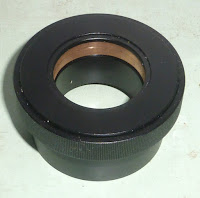
with the dome skirt. The 7" crowned, nylon rollers would have very little lateral friction. So the dome could relax into its natural form. 

I might even find the dome is considerably oval. So that it would not accept being guided by the steering rollers. They might bind. Better to test all of this while safely near the ground. Rather than once the crane operator has it dangling high above the observatory buildings. Completely unable to put it down!!   

The main problem with a raised roller ring is stability. The ground slopes by nearly a foot over the width of the dome. This raises a serious hurdle against mass production of similar trestles. How can I judge the minimum, safe number of rollers? Do I need all fourteen for real world testing? 

I only have six extra rollers. With the remaining eight still supporting the plywood dome. I'd have to make the steering rollers too. Or the whole thing will come crashing down. Using only six rollers probably means a load of 100kg per roller. There is still a large margin of safety for the rollers themselves. Much more doubt about localized loading. Pressing upwards, under the base ring/bracket/bolts and slit ribs. 

Trestles would need a decent footprint to resist tipping in any direction. Then there is the matter of lifting the dome. I am used to using a 2x4 to lift a small section of the skirt. Though only a few inches at most. The dome is stiff enough to lift as a whole. It doesn't flex in any meaningful way. 

It would need fixed trestles for safe and stable support. Then more trestles with the rollers fixed on top waiting inside the dome. Ready to be slipped under the base ring when the dome is high enough. How tall should these trestles be? Four legged 2x4 constructions?

I have caravan, parking jacks but they have foolishly small footprints. Very unstable! I have several, double, pilot wheel, trailer jacks. These could lift the dome by a much greater distance. Though they'd need a solid, dome sized frame to be stable. Just moving the dome segments down the drive on these proved to be a complete disaster. This was due to the torque they applied to the timber frame when the wheels were at right angles. The jacks must be placed on opposite sides of timber rails to balance out the torque.  Difficult to do when there are so few of them! Only four, to be exact. 

They have the claimed load capacity for the entire dome. However, all those wheels might give the dome the daft idea to head off downhill! If I placed these wheeled jacks between parallel 2x4s there should be no torque. I could easily replace the wheels with wooden blocks. That might work if I can clamp these jacks efficiently. Drilled hole through spaced pairs of 2x4s and clamping bolts? Lose the supplied clamps? 

The advantage of the trailer clamps is easy adjustment of height by loosening the lever. Though that requires a very strong prop. To allow the jack wheels to drop freely to the ground. 

Unfortunately the clamps are side mounted. Which forces heavy torque onto the clamps. Even ignoring the heavily offset [castoring] pilot wheels. The combination of offsets is a piss-poor design. Even a small car trailer, supported by the pilot wheel, shows serious twist in the towing beam to which it is clamped! It ought to be placed between the towing members. Not hanging off the side.


*