25.6.18

Dome building: Onwards and upwards.

*

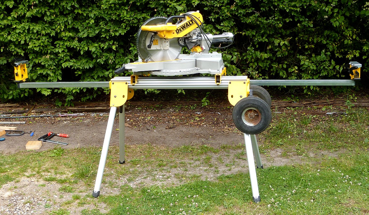
With the miter saw and its stand now mobile I could wheel it outside and under the awning. By lunch time I had cut eight vertical struts for four ribs. The disk sander helped beautifully when I needed a near 60° compound miter with a 20° vertical component. I dropped the sander's table 20° and set up the miter gauge for effortless accuracy. All very satisfying after the earlier struggle with the miter saw in the cramped shed. 

There is still the problem of matching the struts' bevels to the needs of the covering panels. So I haven't fixed the struts yet. I shall have to lay a straight edge across the struts to check the angles required.

It reached a scorching 72F in blinding sunshine as I plodded on. I managed pairs of struts for 7 ribs this afternoon. It looks as rough as hell at the moment because the ribs haven't been flattened to match the struts yet. It will look much smarter after a severe sanding to even everything out.

Overhead image of the dome from the veranda at observation platform height. The dome seems strangely "tall" from this perspective.

Tuesday: I carried on cutting the struts for the upper tier. It became very warm at 78F in full sunshine. I am getting used to bringing the saws out and parking them under the awning. Though that doesn't provide the shade I had hoped. The nylon material actually seems to radiate the heat of the sun. Or lets it pass unhindered. Fortunately I was able to escape for a cycle ride to do some shopping. It is much cooler having a headwind instead of calm conditions in this heat. The constant attacks by gnats and horse flies don't help!

Wednesday: Full sun again and it had already reached 76F by 10am. 78F by 1pm. Still undecided on which glue/sealer to use.

Thursday, Friday & Saturday. Pottering on with adding struts to the top tier. Extreme angles make the job more difficult.

Narrow spaces between the ribs made removing all the screws very difficult indeed. The screws had to come out to allow the gores to part. The image shows the struts after gluing and clamping. The struts can't be screwed on except from the rib side. The ribs are inaccessible until the gores are separated. Another catch 22! Hence the glue to hold the struts [stiffeners and gluing surfaces] in place.They must all come away cleanly from the slit frame ribs or the dome will not separate into gores. Ran out of PVA glue before the last struts were fixed.


Click on any image for an enlargement.
*

22.6.18

A detour: Mobilizing the DeWalt miter saw stand.

*
Having become thoroughly sick of struggling with the heavy miter saw, just to cut longer lengths, I resorted to common sense. The saw would be made mobile enough to EASILY take it outside and back into the shed again. Including clearing the steps and threshold.

I just happened to have a pair of sturdy pneumatic wheels and their solid 16mm axle from a cheap sack truck which had literally rusted away.  It just needed they be fixed to the DeWalt stand without obstructing themselves or the vital levers and legs. The size of the wheels is perfect for mobility on rough ground and gravel. Some mobile saw stand makers really penny pinch and make the wheels far too small for rough ground.

Holding up the wheels on their axle against the stand showed they needed to be the correct height to miss the legs of the stand. Too low and they hit the legs and would rub as they turned. Too high and the material support bar locking lever was blocked in its arc. A large piece of angle would work as as an axle support bracket.

I had no angle alloy big enough to sacrifice. So I cut a piece of scrap aluminium box section in the miter saw to make two pieces of angle. Then rounded off all the corners and edges with a file to avoid cutting myself while handling the profile.

Two holes had to be drilled in the yellow end plate of the saw stand. Placement was important to miss the internal leg support brackets and the leg release levers. I used two sturdy 16mm cable brackets to hold the axle. Since all loads would be pressing upwards, against the angle profile, these clamps should be perfectly adequate.

The trick to easy lifting is to pull out the material support arms to act as long, lifting levers. The arm on the wheel end is lifted at the far end and the legs unlocked and folded up. They are still easy to reach while supporting the saw and its stand with one hand. One the legs are locked up that end can then be safely lowered onto the wheels and the long arm retracted. There is really no need to fold the other pair of legs because there is plenty of ground clearance to walk the stand around. Only if steps need to be overcome would it really be necessary to fold them away.

I lowered the saw mechanism and locked it into place to lower its C of G. Just in case it felt like tipping sideways on the garden's odd cambers during a first test run. In fact it was quite stable and never gave any cause for concern.

Mobility could be considered adequate now but I want to be able to park the saw and its stand, on end, for more compact storage. So a pair of support blocks will be required. A pair of comfortable handles for pushing and pulling would also add to the fun. These will be fitted to the extendable support bars when I come up with something suitable.

In retrospect I should have put the wheels the other end of the stand to make parking easier inside the shed. It is only a matter of drilling two new holes but I'll wait until I can park the saw and stand upright first. It my prove unnecessary to change ends. The saw can't be simply rotated on the stand. It is handed on its support brackets or the material support arms will badly misalign with the bed and fences.

I can claim no new insights for this useful mod since many saw stands have wheels already. It just needed to be put together in the right way. Some mobile stands demand a bent back lift to get the wheels off the ground so that the legs can be lowered and locked. This is not sensible when the long, material support bars are perfectly placed. They are strong enough to cope while providing a far more comfortable lift. The DeWalt, leg release levers make it easy to unlock the legs while supporting the weight of the saw. The wheels and angle bracket do not get in the way of the leg lever operation. Nor the extendible arm, lock and release lever.

I did swap ends with the axle bracket and wheels. I also cut some 2x4 timber into a quadrant to ease the climb over the threshold. Though 45° is far from ideal. The contact point with the tyre is almost unchanged over a vertical bar of the same height. Making the hurdle, to be overcome, just as severe. I shall have to re-cut the wedge to a much shallower angle.'

Next day I re-cut cut the ramp wedges to 30° and this made all the difference. The loaded saw stand will rest on end if the lower material support arm is pulled out a few inches and locked. Though a sturdy crossbar would be more useful for greater stability. My cramped saw parking space won't let it topple sideways but I'll look into the problem anyway.

Click on any image for an enlargement.
*

18.6.18

Dome building: With perfect hindsight.

*

Monday: It is 66F, overcast and windy today so I am pottering on steadily. Today I added more 6mm [1/4"] screws, oversized washers and nuts to bring the tally to 9 per paired rib. Another screw will hold the upper ribs together when they are completed to bring the total to 10. 

The ribs are 9mm thick birch ply so become 18mm [3/4"] when bolted and bonded together. The vertical struts reinforce the ribs to make a remarkably strong framework. The horizontal ribs add stiffness by preventing the ribs from bending to left or right. 

By duplicating the ribs, the gores were entirely independent of each other. Building a dome with ribs alone relies on their accuracy and the covering "skin" for strength. Once started, the typical hemispherical dome is a full size model and most of its weight  already present. My [insane] method is more of a "belts and braces" approach. Though at the expense of much greater complexity and hand fitted parts throughout. 

However, my dome can be easily separated into gores, base ring and slit frame as desired for transport, detailed work or shelter from bad weather. The individual gores can also be easily managed by a single person. Even carried 'upstairs' for final assembly. The smallest completed dome requires a gang of willing helpers or a crane for lifting into place. My dome is still manageable [by a single person] until the ribs/gores are finally glued, bolted and sealed together, in place, upstairs, on top of the rotation wheels, 15' above the [made up] ground.

This image  from the inside shows the smaller gores on either side of the observation slit ribs. My choice of ribs + struts construction allowed me to use the ribs for guidance as to the spherical shape of the gores.

In retrospect I should have relied more heavily on identical vertical strut lengths instead of cutting each to size. That would have ensured greater accuracy of the individual gores. Instead of which I had to make the gores to match the next one along. Whenever I re-cut the horizontal struts [to unwanted close gaps] it would change the shape of the dome. Causing the top to sink or rise unexpectedly. The dome itself was so stiff it would not allow me to cheat anywhere.

The horizontal struts were a nightmare to cut because of the compound miters and length being so critical. When a row of horizontal struts was the wrong length they forced gaps between the plywood ribs at that level, above or below. To add to the misery, the plywood ribs were much too flexible to be fully trusted.

I had to cut the ribs across the width of the 4'x8' plywood sheets or the waste would have been horrendous. Not to mention the difficulty of cutting them "out of the solid." Again, with the perfect vision of  hindsight I should have used slightly thicker ply and cut the ribs to full length along the stiffer direction of the sheet.

I had hoped that the ribs would meet the slit frame before they ran out. They didn't. Not by 18" or so. Adding rib extensions has been a real struggle and is still far from over. I have not enjoyed this stage of the build at all.

With stiffer ribs I could have cut them all accurately and identically to shape including the "flats" for the facets.  If I was doing it again I would use a very stiff radius arm and plunge router to cut out the ribs along the sheet. The cost of the ribs would probably have been doubled and birch ply is not remotely a cheap material! Hundreds of pounds/dollars equivalent in extra material for the ribs alone!

An image of the dome drying after a heavy shower when treated with mineral powder wood protector. Cosmetically I could almost live with this "weathered" finish as it darkens further with exposure to the light. It still has to be properly sealed or it will leak like a sieve and is very likely to rot and fall to pieces. The discussion on a suitable sealer is ongoing.

I have spent weeks experimenting [and struggling] with different strut lengths and angles to reach this point. Only the miter saw has made this possible. The ability to shave small increments allowed me to succeed at the cost of wasted time and endless frustration. Then the table saw, with its vital DIY sled, allowed me to shape the panels to the actual dome skeleton. When in reality they should all have been identical on each tier!

Now I have the gores bolted together, but still not glued together, I can run an angle grinder over the inside of the rib pairs to match the curves to a single arc. The ribs were each roughly cut out using a handheld jig saw rather than a router on a stiff radius arm. Or even the bandsaw out of doors where there was room to swing a full rib arc.

Due to the covering panels there isn't room now for a router to trim back the inside arcs of the ribs to perfect uniformity. Though it could still be done by separating the gores. It made plenty of noise but I finally evened out and matched the inner arcs of the ribs. A 24 grit carbide disk in the angle grinder followed by a 36 coarse sanding disk and then an orbital sander to round the shoulders off.  No more sharp edges or protrusions to catch long telescope dewshields. The ribs will probably be used as handles for shoving the dome around. So rough edges and splinters are best avoided. Many domes have handles to aid rotation but they have to be found in the dark. Ribs are within reach everywhere.


Click on any image for an enlargement.

*

16.6.18

Dome building: Vital saws and stands.

*

Friday: Continuing with the framing and paneling of the dome around the observation slit frame. I had to cut up my last sheet of 4mm birch plywood to get wide enough strips. Which leaves a lot of waste. I will have plenty of material for the top ring of panels. Three more panels and the third tier is complete.

The miter saw has made this project possible. With weird compound miters on each end and precise length requirements on each strut. So I would never have attempted such a design without owning the miter saw. Just being able to shave a tiny bit more. Or to change the angle slightly. Is an amazing improvement over any other tool I have ever tried. Experience obviously helps and can save a lot of time avoiding taking many, very small cuts.  

The table saw sled is an absolute revolution in my cutting skills and accuracy on thin 4mm birch plywood. This is regardless of all the power tools I own now and have owned for decades. The DE7400 rolling saw stand has made my use of the table saw completely practical. I have to roll the heavy saw along the central corridor of my ridiculously cramped shed. Then do a tight 180° by the even narrower doorway. All just to clear the raised threshold and outside step. The journey has to be repeated, in reverse, on my way back after using the saw. 

Practice makes perfect and it gets easier each time as I learn knew tricks of balance and where to push and pull. This freedom of movement has allowed me to make sawdust outside where I need to cut large sheets of plywood. I just set up two B&D workbenches with clamped rails to support the large sheets during their movement through the saw. Though three stands and rails would be better to support long and floppy strips of wavy, 4mm ply.

The miter saw lives on a long fixed stand in the shed and is an absolute pain to use just there. I have to bodily lift and drag the saw and its silly stand out by a foot or more by scuffing the widely splayed feet along the floor. All this just to clear the ends of the stand for longer work pieces.

The miter saw is just too heavy and too awkward for me to carry about regularly. I simply could not use it at all if I had to take it outside each time. Another DE7400 rolling stand might make real sense for this saw if I only had room to park it. I could then mount my Inca band saw and heavy disk sander on the DeWalt fixed workbench using the matching, universal, Q/R brackets.

EXCEPT! That these two saws need very different stand and working heights! Image below left shows the problem. On the DE7400 the miter saw is knee high to a grasshopper! The much taller, miter saw, fixed stand is in the background.

After struggling to get all the kit outside it started raining hard just as I tried to snap the differences. The miter saw must have a different [rolling] stand [and has.] But not a compact one like the excellent example under the table saw. Note the wide disparity in Q/R support brackets. The miter saw stand has a single rail. The table saw two widely spaced rails. Don't order the wrong brackets or you'll kick yourself.

Several drooling idiots on YouTube call the rolling, table saw stand a miter saw stand. If only it were true! The ridiculously oversized and complicated, tubular, DeWalt miter saw stand looks like a mad inventor's ironing board on steroids. It has a very poor record for reliability of the gas strut which is supposed to lift the top section with saw attached.

Interestingly, the fixed stand can be easily fitted with wheels for mobility. There is even a commercial kit in the US for adding wheels. I my look into modifying my own stand. The extending, material support arms can be used as leverage to move the stand around quite effortlessly. [If the owner has enough room.] Or, to lower the legs with the saw still in place. This offers a safe way to lower the saw and stand down onto added wheels.

Meanwhile, back in the shed, the fixed stand, with bandsaw and disk sander attached, could be pushed much further back until the feet contact the wall. The slide mechanism on the miter saw sweeps a very large radius both front and rear. The rear overhang, even without a vacuum hose or dust bag fitted is huge. Which means it can easily hit the back wall during large horizontal angle adjustments. Unfortunately the table saw will not easily park under the fixed stand on its rolling stand. Perhaps I could fit large riser blocks under the rubber feet of the fixed stand? Or perhaps not.

If only two, large, birch trees hadn't been growing just there, when I built the shed, I could have added several more feet to its width. Once the 30" deep shelving unit is fitted on the right there is no room to swing a cat. Let alone a 12" sliding, miter saw. The trees have finally gone but now there's no room for expansion with the observatory building in the way. The octagon is far too small for sawing up sheets of plywood and the dust would be a bore anyway.

Sunday: Completed the last three of the third tier of trapezoid covering panels. Then  had a look at my Inca bandsaw. It has lived on a shelf in a large rack which made using it unnecessarily difficult. I was having to wrap my arms around the rack's corner support post. Which was very limiting and made cutting larger pieces impossible unless I rotated the whole saw body midway though the cut.

I need to have a freestanding arrangement for this saw to get some real use out of it. While I was cleaning it I rotated the entire motor on its axis to bring the On/Off switch to the front. Band saw owners should check the Snodgrass blade and guide set-up method. All very logical and sensible. I discovered it on YouTube after years of haphazard fiddling with my saw's settings.

Click on any image for an enlargement.

*

13.6.18

Dome building: Same dome another week.

 *

Sunday morning it cooled off from early warmth to 66F. So I painted the skeleton with Safeway mineral wood preservative. The powder is added to cold water at 5g per liter. The powder does not thicken the water so it goes a long way but can be messy with spray form  brush used with a little too much enthusiasm.

When it started raining quite hard the awning kept the dome completely dry so I went on painting. The dome is now "weathered" just like an abandoned barn, inside and out. It will be painted properly, of course, but the treatment might just prolong its life. The popular GRP covering beloved by amateur dome builders would add considerably to the cost and weight! So I'm hoping that high quality breathable, wood protection paint will do the job instead. I put the panoramic "after" image together using MS ICE.


I asked at a builders merchants what they suggested for sealing my dome panels. Dana MS522 [or 524] was their recommendation which is not very expensive. It has been available for 20 years and the seal around some original window installs, in the harsh conditions in North Jylland, are claimed to be still as good as new. I'm not quite sure that a sealer used around fixed windows is exactly my need. A higher degree of flexibility is desirable where the dome will be buffeted by wind and rotated on a non-perfectly smooth ring. Most materials stiffen with cold and there will be cold aplenty in most Danish winters. Most adhesives/fillers/sealants harden with age. I haven't pinned down any of the latex-silicone-acrylic sealers which are widely available in the US market. Even eBay[UK] dealers list them only from the US.

There was some discussion on the width of the gaps between panels. The smaller the gaps the more flexibility required. I went with edge to edge fitting when cutting the panels on the saw sled. It occurred to me that I could take a small cut across the bottom of each panel. The panels would then all be slid downwards by only a couple of millimeters. This would provide an automatic peripheral gap on all sides without altering the trapezium's other angles.

I thought I'd see whether a boot scraper style, galvanized steel doormat would work as an observatory trapdoor. The reality was the weight rises rapidly with size. Forum members suggested aluminium or fiber grills. Both are available in Denmark but costly in typically large sheet sizes. I only need 50x100cm maximum length. I may be able to source more locally from a user of these products rather than a wholesaler.

I looked at making another larch floorboard trapdoor and reducing the weight by using a hole saw. The maths doesn't add up to a very lightweight trapdoor. Pi.r^2.N but at least it would breathe. An alternative would be a sandwich of polystyrene and plywood. A stiffening wooden frame would be concealed within the footprint. The cosmetic clash with the larch flooring would be rather obvious.

Framing around the small gore beside the slit frame. Not only must the length be perfect, but the ends are compound mitered [all to different angles] The large face bevel must also be made to exactly match the slope of the attached panels. The slit frame will eventually be cut back in straight lines to match the sliding shutters to the panel tiers.

An open grating [trapdoor] would allow free air movement for a chimney effect to clear warm air from the dome. It would be safer than leaving a solid trapdoor open in the dark. Or leaving large doors open in the Western observatory wall. It was suggested I rig up a red light to show the trapdoor is open. A roller micro-switch could do the switching. LEDS can provide low voltage, low level, compact lighting which can be easily concealed from direct view. AC aluminium floor grills aren't so obviously available here compared with the much warmer US.

I ordered another 100 6mm [1/4"] stainless steel screws, nuts and oversized washers to hold the ribs more firmly together. They will help to spread the loads across a much larger area of rib.

Thursday: Spent some hours rebuilding and fitting vertical struts to the narrow gores beside the slit frame. I also reworked the slit frame base to close gaps and square it better against the dome. Rain is forecast for this evening so I have covered the dome with a lightweight tarpaulin. It did rain quite hard so it was well worth covering up the dome.


Click on any image for an enlargement.

*

7.6.18

Dome building: One big lift or little lifts?

 *

A year on and quite unbelievably, I am now suddenly closer to placing a dome "upstairs" on the prepared and now weathered observatory building.  I had planned to hire a Manitou MT1135 which has massive overcapacity in reach, height and load. The next smaller hire MT625 can't lift the dome high enough nor reach out far enough to clear the building, mounting and veranda.

The dome has considerable self-height which would dangle below the lifting "hook." Plus any rope extension or strop stretch. I'm still juggling with ideas for safely supporting the dome for the lift. Ropes or lifting strops would need serious overcapacity and careful arrangement.

I need to avoid imploding the dome with inward forces and there really isn't much to tie onto. I would imagine the need for a trestle arrangement under the base ring to avoid stressing the dome itself. That raises the problem of clearing the support wheels and its removal after the lift. Lifting by a sturdy crossbar lodged under the open slit framework would be very risky to the integrity of my dome construction. A dome is strong in compression but can fly apart with unusual lifting forces.

Now I'm talking myself out of using a telescopic loader and re-considering carrying the gores upstairs myself. I could easily build a temporary 2x4 jib "upstairs" and use my boat winch to effortlessly lift the gores one at a time. That would put me, and them, in a far better place for rapidly adding them to the prepared base ring & slit framework upstairs. I only need to be inside the dome to assemble the gores together. So my usual stepladders are fine. No external, aerial acrobatics on tall ladders or tightropes required. Guinness will be so disappointed but I didn't have odd coloured socks to wear anyway.

I have already lifted the base ring onto the support wheels twice and brought it back down again. So I know that's doable. The gores are numbered and should drop straight into place on a level base ring. With the prepared and safely supported slit framework already fixed in place. I've had loads of rehearsals putting the dome together on the ground stands. I even removed a complete gore yesterday just for weighing. Say about a quarter of an hour total for removal and refitting. The stainless steel bolts went through the ribs effortlessly thanks to drilling 1/2mm larger clearance holes. I've spent a lifetime trying to force bolts though the same size holes as themselves!

I'm assuming the gores will be completed and sealed as separate units before lifting individually. That would just leave sealing between them before bolting the gores together upstairs. Painting could be done on the ground or later with a roller on a stick. I'm rambling a bit here but wanted to point out the potential difficulties and advantages of each lifting approach. Even if it is only another script reading rehearsal for myself as the solo act.

The wind and weather are important factors. The weeks of fine and sunny weather could easily change. High winds need serious consideration. The dome must be rotatable to avoid spinnaker effects when only half assembled. So I should seriously consider having the shutters ready to go on before raising the dome by either method. I'd better get cracking or ice and snow could intervene.[again]

Thursday update: I finished the last two rib extensions nearest the slit. I'd been putting it off for ages because of the very acute angles. So I dug out the cheapo 12" disk sander and took mere seconds to match the angles and lengths perfectly.

I really need to make my lesser-used power tools much more accessible. Their sheer weight means they don't get lifted off the floor from under loaded shelves and junk. If I don't use them, often enough, I can't practice to become highly skilled at using them. I sanded the ends of the ribs while crouching on the shed floor. It doesn't have to be like this. Too much junk!

Another Thursday update: Somebody of the CN forum suggested I use eye-bolts through the base ring for the lift. That's actually a great idea! Because projection into the wheel space will be minimized on the final lower. I can reinforce the base ring & dome for the big lift with a simple, crossed timber bracing pattern. These will safely avoid the central telescope mounting if I remove the 30" long saddle first. I really don't want to take the heavy mounting down again!

Being relatively short sections of timber the cross-braces will be quite light and easily removed from the observatory once the dome is safely in place. They need only be bolted together for easy dismantling.

I have hardly been doing anything to the dome in the present hot weather as it hovers around 80F. I set up a blue awning but it doesn't reduce the temperature. It is claimed to have a 50 SPF [sun protection factor] but the heat of the sun can still be clearly felt in its shade. It does have the advantage that I am not blinded while looking upwards while fitting components.


Click on any image for an enlargement.


*

5.6.18

Dome building: And then there were three.[tiers]

*
Tuesday, and another hot, 75F day with constant sunshine. As usual I set up the table saw saw under the blue awning for some much needed shade. Cutting out the dome covering panels has become routine. I even managed to get 9 panels out of a single sheet on the third tier. They were all about 50x50cm.

I aimed for close joints and was aided in this by the table saw sled. My hope for crisp angles and flat facets was rather spoilt by the softness of the 4mm birch ply.


The third tier went quickly after my practice on the second. Not one single panel was wasted though there was some earlier wastage from the odd size of the panels on the lowest tier. Wastage, which I hope to use up on the top tier.

Nothing is straightforward though. The top tier should consist of straight lines and flat panels too. I haven't yet decided how best to remove the present curves. A chainsaw massacre? 😉 Not quite. Those rib extensions which could be removed were sawn straight on the bandsaw. The rest were attacked with the jigsaw, where it would fit between the tightly packed ribs. I also used a coarse disk on the angle grinder to cut back the remaining projections.

While I was out there I removed one complete gore to weigh it. About 8.75kg = 19lbs. Let's call it 20lbs per gore when completed and painted x14 = 280 lbs or 127kg. Plus the heavy base ring and slit framework. Then there's the shutters and their rails on top of that. A skirt will also be required to seal the area between the dome base ring and the supporting wheel area.


Click on any image for an enlargement.
*

3.6.18

Dome building: DeWalt Stop button paddle.

*


I have decided the required electrical mods are beyond my skills to achieve safely with this stop switch. So I went with a hinged, mechanical "paddle" to push the saw's original OFF button instead. This ensured that DeWalt's safety features and original wiring and components were used without my amateur modification. The paddle would provide a nice large "target" for my fumbling at the end of every cut. Whereas the tiny, DeWalt OFF button is a complete waste of space and foolishly dangerous. I have no idea how they got away with not providing safe or even adequate switching.

I needed to fit a hinge somewhere at the top of my paddle but was loathe to drill holes in the saw's plastic bodywork. It was then that I discovered I could trap one flap of a modified hinge under the original switch panel. This proved firm enough to work well using the two, original upper screws on the switch panel.

Then I added a perforated roofing plate as my hinged switch "paddle." Its rocking movement is deliberately made very short. This needed a rather precise bend in the plate to bring it close and almost parallel to the ON/OFF buttons. I made too soft a bend at first which put the plate much too far away from the ON button. I still needed to reach the ON button easily and without "training." Hence the precise geometry required at the bend.  

The plate also required cutting away at the bottom to fit around the Q/R DeWalt stand supporting brackets. I also had to cut away part of the hinge to fit within the plastic bodywork groove around the recessed switch panel. Having the hinge slightly skewed looks wrong but proved essential to clear the stand bracket reliably.

Making a hole large enough to easily reach the ON button with one finger took a lot of filing. I should have daisy chained a ring of holes and saved myself a lot of time had I know how large the hole really needed to be. Eventually I had the plate switching off the saw effortlessly with almost no free movement. Nor, importantly, with the pusher actually resting heavily on the button. This might cause rapid wear through vibration or even switch off.

The OFF button is depressed by a stainless steel carriage screw with a large, smoothly domed head. I didn't want a pusher which would wear away the button's clear protective covering in the long term.

I shall screw a plate of bright red plastic to the face of the perforated plate when I can find a suitable donor. Perhaps a kitchen or hobby cutting board if I can find the right colour.

After using the saw with the new OFF paddle I'll be looking for an embossed surface for more tactile feedback. I found I was unable to decide whether I had actually found the paddle each time I wanted to stop the motor immediately after making a saw cut.

Hey presto! A secondhand, red cutting board with a tactile surface texture. £1 equivalent from a charity/thrift shop. Only one side was marked so I  turned the pretty side outwards. The switch paddle works a treat and easily works with a knee press when both hands are busy holding onto work on the saw table.

The earlier cloud has dispersed as today's temperature reaches 76F in bright sunshine. Twelve lower panels are carefully fitted but now I've run out of 4mm birch plywood. I shall have to make the 20 mile round trip to the builders merchants tomorrow with the trailer.

I'm only getting four dome panels per 150x150cm sheet with nearly 1/3 of a sheet "wasted." This waste can only be used up on the very top panels. Even the shutter will need much larger panels. Fortunately the higher tiers are only 49.5cm in height. Allowing 6 panels per sheet.

Monday: I fetched three more sheets from the builders merchants so should have enough to finish the dome covering panels now. Sawed them into 50cm wide strips using out-feed rails clamped in work benches. The desire is to keep the blade low but the wavy plywood is difficult to keep flat enough.


Click on any image for an enlargement.
*