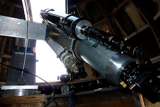
30.6.19

30th June 2019 Earthing the mounting 2.

*

Since I couldn't find a suitable nut to protect the top thread of my shiny new earth rod I used a 16mm, domed nut as a close fitting cap. This survived right until the last couple of blows with the lump hammer. Then the top of the brass dome gave up and fell off. To reveal the naked top of the earth rod. The hammering had gone very smoothly. All two meters [6'6"] had descended out of sight without serious resistance. It probably only took about five minutes in all.

I then stripped the end and and clamped up the impressively thick, 6mm^2 earth cable to its brass clamp. Then clamped that firmly in place inside the protective metal, rain hat. Which, in turn, wedged the brass clamp solidly against the earth rod. I then clipped the heavy earth cable up the leg of the 14' pyramidal pier. More clips avoided the cable "shorting" the isolation between the pier and the observatory floor. 

Rather than making a fresh hole I removed one of the flanged, furniture nuts: Fitted a large washer under the flange and then clamped the stripped end of the earth cable under that. The thick, stranded copper is squashed flat and intimately contacts a large area of the hefty, 10mm aluminium plate of the polar bearing housing. Every other part of the mounting is in intimate contact with this assembly so the entire mounting is now well earthed. 

Given the 60VAC potential leaking from the AWR 12V power supply earthing is probably a good idea. I could feel this potential with my fingertips whenever I touched the mounting or telescopes. It also lit the neon test screwdriver. After earthing the difference between the mounting and the big stepladder was down to 3VAC @ 50Hz. My new [inexpensive] multi-meter has finally arrived. The old one was reading about half the correct voltage and the big digits were losing bars.

I made a discovery about my 4TB USB3 external drive. Which I had bought to cope with the solar video capture, production line. Though, so far, there is only my 230GB of my still images in there.

I had initially plugged the HDD into the only free USB socket on the back of my PC. Which, being jammed into a narrow gap beside the desk and in a corner, was almost impossible to access from above. My wireless mouse cursor kept freezing, despite new batteries. So I knew something must be wrong somewhere.

Finally I ran out of patience and tipped the PC on its front plate. Now I could carefully examine the tight cluster of different sockets hidden away half way down the back. All of which I hadn't seen for at least a couple of years. I had never really needed them before because I simply hadn't any USB3 bits to connect to until now. It's a shame they didn't put USB3 on the front plate too. The sockets on the back are too inaccessible to be useful for plugging in the SSD when I have videos to transfer from the laptop to the PC.

Fortunately I was rewarded with the sight of several, unmistakable, blue, USB3 sockets on the back. I did a quick swap around of assorted cables in order of priority. Moved the mouse and keyboard wireless dongles and the HDD is now behaving itself impeccably. Everything is back to snappy functionality. The constant uploading to MS and Google cloud image storage, via the slower USB2, was probably partly to blame. Anyway, lesson learned and yet more problems solved.


*

29.6.19

A Green dome or a white dome?

 *

The green paint on the outside of the dome is providing intolerably warm conditions inside. From the inside, the southerly range of dome panels feel like radiant electric fires! This is just from the sun's heat being absorbed by the paint then passing straight through the thin plywood.

I opened the double doors out to the veranda, the doors on the ground floor and left the observing slit wide open all day. It didn't help very much and I did not enjoy going up there for more than a few seconds at a time. The images through the telescopes were visibly "boiling." Making it rather pointless to observe or try to image the sun.

My wife is very much against my painting the dome white and I can see her point of view. It would certainly become far more visible from a far greater distance against the overall, green backdrop.

Presently the dome can just be seen from very narrow viewing angles thanks to local trees and hedges. Being dull [sage] green it doesn't attract much attention to itself. The building is dull brown below. With multiple, angular surfaces to avoid large blocks standing out. It works too!

The multi-paneled dome really does present very different surfaces and hues in the ever changing light. The green paint changes from pale to dark depending on the angle of view and the incidence and reflection of the light or sunlight. The dome and veranda both throw shadows onto the walls below them. The octagonal walls endlessly change their appearance with the changing light. Not quite truly camouflaged but close enough for my needs. The background trees change constantly too. Depending on the height and intensity of the sun, any cloud, shade or wind orientating their leaves.

A white dome would instantly end everything in my favour so far. It would become visible, like a beacon, from afar, from the air and from space. Denmark has lots of free, aerial imagery services both governmental and commercial. While it may be a low crime country, there is no point in waving a big white flag to potential, or merely curious burglars.

Imagine uninvited visitors turning up in the drive and asking for the official tour? I might even have to start tidying the dome and lower building! I might also need 3rd party insurance against personal injury. Just in case somebody inexperienced tries to stand on the invisible glass in the middle of the trapdoor cut-out in the observatory floor. Eek!!

*

Far Too Remote?

 *

Years ago I argued on Abusenet with those who suggested viewing the night sky via the new-fangled "night vision" cameras fixed to telescopes. Far too "secondhand" I felt at the time. I was only interested in pressing the MK1 eyeball to the eyepiece for its "immediacy" and direct connection to the universe. Via the intervening optics of course.

Later on I started taking SLR film 'snaps' of the moon at the eyepiece. Just as a [poor] record. Later again, I started taking lots of afocal snaps using P&S digital cameras. A vast improvement over film and cheap as chips to take literally hundreds of trial exposures. Now I had something I could share online.

Later still, I captured videos via a webcam. Or slightly more sophisticated astro cam and software. Had you told me, years ago, how fascinating it is to watch a computer screen with a razor sharp "live" image I simply would not have believed you.

That said, I am sitting comfortably beside my own pier and soaking up the ambience of my own, observatory dome. My telescopes soar overhead and I can pretend I have some [probably imaginary] historical association with a long line of past, amateur astronomers.

Can I make the psychological jump to watching a "live" image from some other, more distant [remote] telescope? Or is it one too many steps removed from visual? And one step too near to everyday TV watching?

Who knows what rapid advances imaging and screen technology will offer just down the road?  A much bigger, 4k/8k screen in place of my present 15.6" 4k, to provide much greater immersion, might just tempt me to go "remote" on lunar and solar. If only now and then. The image quality and seeing would have to be truly exceptional though. Better than anything I can possibly manage alone. 


*

26.6.19

A martyr to solar gain.

 *

Wednesday: I went up to the dome do some proper measuring using a Laser-Line thermal measuring gun. This shoots a laser dot as a pointing guide and measures the surface temperature around the projected spot. Note that the further away the gun is from the surface the wider the measuring area. Think of it like a cone spreading out from the muzzle of the "gun." Best pin-point accuracy is within a couple of feet but usually unnecessary in practice. The manufacturers missed a trick in not providing further angled spots to indicate the measured field width.

The air temperature inside and outside the dome was 85F/80F today in bright sunshine with thin, high cloud casting only occasional, weak shadows. The outside thermal sensor is hidden in an open section under the NE veranda floor. It hangs freely in mid air where the sun can't ever reach. This veranda floor area is either in the shade of the adjoining shed roof or that of the dome or its supporting building. I have two other free air, shaded sensors on other, digital thermometers and they usually all agree with each other.

Since both buildings are largely constructed of timber and clad with plywood there is no thermal build up. Nor thermal storage to affect the air temperature readings in the shade. The inside dome thermometer head is mounted on the north side of the telescope pier. About four feet from the observatory floor and never in direct sunlight.

The highest dome panels, perpendicular to the sun, measured 130F /55C [!!!] on the inside measured at about 8' distance. The further down the dome the lower the panel temperature readings. The further away from the sun's direction the lower the panel temperatures. Which is exactly as expected.

The bottom dome panels to the SE [sunny side] measured 115F. The bare, unpainted, 15mm plywood walls, again to the south east, showed 100F. The northerly observatory walls measured just 84F. The northerly, lower dome panels 90F. The observatory walls, being vertical, are not perpendicular to the sun.

Bearing in mind today's air temperature in the low 80sF, the almost constant sunshine and the green paint it is no surprise how hot the dome panels really are. If the sun goes behind a cloud the panel temperatures would drop rapidly. Plywood has poor thermal storage capacity. Experience shows that the dome cools quickly when thick clouds intervene and the slit is open to allow free air movement.

Options to reduce inside temperatures include increased air movement through the walls. I have some large louvered panels which could be set into obs. wall panels to make a through draft in a breeze. The observation slit provides a large area for heat to escape right up to and over the zenith. The downside is that it is often uncomfortable to sit in a breeze. So the louvered panels would need to be fully sealed when not actually required.

I have tall, decorative, deciduous shrubs growing in front of the southerly and south western side of the observatory. These have already reached the veranda floor in height and will grow and thicken further over time. A similar shade shrub would need a large pot to grow in the SE corner between the obs. building and the shed. A conifer might be better and could be rolled about in its pot. To increase or reduce the amount of shade or simply to adjust for growth in girth.

Shading the dome itself would be a better idea but very difficult to easily arrange. The dome slit must obviously be opened for seeing out. Not to mention rotated to follow the sun. The veranda fence could be covered with shade netting but its shadow would only cover the veranda floor at this time of year. Making the exercise completely and utterly pointless. The veranda floor shades the top half of the lower floor of the obs. building. Nor very useful at reducing the upstairs obs. temperatures. Where it really matters.

More difficult and advanced shading could involve fixing louvers on the upstairs obs. walls to cast solid shadow but allow air movement. Some adjustment of the individual louver's angle would allow the degree of shade to be matched to solar altitude. It would only be useful on the southerly run of walls as the sun never [ever] reaches the northerly arc.

Placing louvers on the outside of the dome would be ridiculously complicated by the changing angles to the vertical and horizontal. An exo-skeleton of standoffs would allow shade netting to be fitted to the outside of the dome. Though it would not be a remotely easy exercise. Not least because of the difficulty in reaching most of the dome. Laying the net directly on the dome panels would probably just trap the heat inside the net. Fortunately net has very low drag in winds. Not sure about countless louvers in a gale.

I once considered a roll-off dome, on rails, but the telescopes project so high and wide that they would not clear the present observing slit as the dome was pushed away Westwards from the obs. building. The dome could be split in two and be moved both east and west. The difficulty of achieving this safely would be monumental. Or just, plain, old mental.

*

25.6.19

Earthing the mounting

*

To vent my frustration with my first try at FireCapture I banged a 1.5m [60"] length of 20mm [3/4"OD] galvanized steel, water pipe into the ground. I positioned it at the foot of one of my 14' tall, 4"x4" pier legs. I reasoned that if the ground is still damp under the gravel, inside the building. Then it will still provide a good earth but will be protected from lightning. Rain falling outside the observatory building helps to keep the whole area under the building damp. The 2" of "pea gravel" keeps things clean, dry and tidy on the surface.

I had screwed on a steel end cap before going to work on the pipe with the lump hammer. This was to protect the threaded end of the pipe from the hefty hammer blows. It took only ten minutes to sink the pipe until only a couple of inches remained visible. The cap unscrewed easily enough afterwards. So I put it in the lathe to bore a 12mm hole centrally in the top. 

The hex from a 12mm bolt head was turned to a slight taper to clear the inner diameter of the pipe. Passing the bolt through the hole in the cap will act as a cable clamp with a big brass washer under the nut to increase the contact area. The tapered bolt head will jam in the pipe as the cap is screwed on hard.  Further increasing the conducting surface area over and above the tightened threads between the cap and the pipe.

The pipe and fittings are galvanized inside and out so corrosion will be very slow. I suppose I could grease or oil the threads to slow the build up of rust. An outer, screw clamp will ensure the earth cable enjoys even better conduction to the earth pipe.

The pipe went down so easily I am tempted to buy a longer length of 20mm OD [14mm bore] standard water pipe. This will help to increase the earth "rod's" surface area. Reaching even deeper into the wet, clay soil below the two feet of still damp, self compacting sand and gravel. Which I had used to raise the ground surface for the building to match the level of the parking area in front of it. 

It seems I am much better at such simple mechanical tasks than working with new imaging software! Or perhaps I was just very lucky with my exact siting of the earthing rod? Interestingly, my cheapo multi-meter measured the same 60V potential on the mounting when I connected between the temporary earth rod [pipe] and the mounting. 

In the interests of safety I have decided to order a "proper" earth rod 2m [6'6"] long x 14mm [~0.55" or 35/64" Ø.] Plus a protective metal top cap with a serious, internal, cable clamp. This was the kit I fitted years ago to my Hifi specific 3-pin sockets indoors. To kill the hum experienced on the normally 2-pin sockets in Danish homes.

6 meters of 6mm^2 green/yellow earthing specific cable will connect the mounting metalwork to the spike inside the building. I will clip the cable to the timber, pier leg to keep things tidy and to avoid shorting out the pier's physical isolation from the supporting building. None of this earthing stuff seems to be available at ordinary Danish, builder's merchants. So I had to buy it all online.


*

24.6.19

Goodbye SharpCap hello Firecapture? Earthing the mounting.

*

Monday 24th June: I reloaded FireCapture onto my laptop from the website after resetting my 4k screen to 1920x1080. Finally I could see the details of the work page but that is as far as it went. It took me ten minutes of searching to find the damned Night Vision/Daylight button. 

I started off with a realistic H-alpha view in typical pink but without the SharpCap rippled mask overlay. Great! Before I knew it my sun had gone mono and was impossible to return to normal. Then it started collecting artifacts and was soon a mess of crossed lines instead of a normal picture! 

The change in screen resolution was not perfect and the menu bar was being overlapped by the active image box. I closed it down to start again and then searched hopelessly for it on my computer. It existed nowhere! A fresh download and fresh settings every single time I want to use it? Life is too short! I even added it to my work bar but that had vanished too! Grr!

*

21.6.19

21.6.19 SharpCap and ZWO woes 2. With YT videeo.

 *

Well, nothing was gained from another full day's online research and practical trials with four different telescopes.

Both the ZWO and Neximage5 appear against a ground glass screen background in white light in SharpCap on both the laptop and my indoor PC with a large [HD] monitor. In H-alpha [deep red light] the background becomes a much coarser, rippled glass effect. The sun's real surface was obscured behind this ripple and the rippled screen was then carried over to the recorded video. Making it impossible to use Registax to produce a sharper image. The ripple can be seen in the first preview image in Registax.

I normally use RGB24 for a larger fields of view for prom and sunspot searches but have tried all the different options of RAW and MONO in 8, 12 and 16, in all frame sizes/resolutions down to 320x320, or whatever.

I have uploaded a 1m video to YT to show the obscuring effect as I drive the telescope around in slow motion. Full Screen makes it easier to see:

https://youtu.be/hHIlU7H2RA0


Note that this is not a moving screen but a static overlay [effect filter] overlaid in front of the real image on the screen. The Sun's surface can be seen moving behind the obscuring "rippled glass" when the telescope is moved or deliberately shaken. There is a definite depth or perspective effect on the laptop screen in SharpCap. The rippled mask does not rotate with the camera. Which suggests that it is undamaged or innocent.

It has suddenly occurred to me that I bought an external SSD to cope with the high speed and large file sizes of the ZWO120MC-S camera. There may be a clue here regarding gain versus exposure times. Debayering or untangling the colour camera's sensor matrix as it reaches the computer software may be the problem. When handled wrongly the effect is similar to seeing a cloth pattern. I see a tartan effect when I really over-sharpen my images.

Imagine a uniform "cloth" pattern but out of focus. It may even take on the form of my rippled mask. In fact the mask lies in front [on top] of the active sensors and tells the computer which colour is represented by the underlying light [grey] sensors. Colour is produced by the camera software. Colour sensor cells are really just shades of grey until the overlying mask confirms the intended colour of each individual cell. Don't take my word for it. I just scanned a few websites to try and get a grip on debayering.  Here's a useful guide just to get you started.

What is Debayering, and why should I do it before stacking my images? | Altair Astro Cameras


Click on any image for an enlargement. 
*

17th June. SharpCap & ZWO woes.


Monday 17th: Sunny and I spent almost the entire day in the observatory trying to capture a prom. No matter what I did my efforts proved stubbornly pointless. I captured videos, worked on them and then deleted them and my resulting stills. Apart from my continuing lack of skill with the stacking software the seeing wasn't really very good. The overlaying ripple was back. I even tried FireCapture and it provided no advantage over SharpCap.

Thursday 20th: A helpful contact has suggested I check the effect of my laptop PS [power supply] on the surface "ripple" I am seeing on my laptop screen when imaging with SharpCap. Without the laptop being present I checked the potential of the mounting which had been tickling my fingertips and lighting a neon, test screwdriver. It showed a 60VAC potential relative to the big stepladder nearby when the AWR's 12V 7A power supply was active. The ladder is not earthed but sits on rubber feet.

I bonded the mounting to the stepladder but can still feel a potential on certain parts of the mounting and OTAs. Presumably these parts are isolated by the bearings or the felt lined, tube rings. An imaging test with SharpCap, with and without the laptop PS being connected, might prove interesting.

I have now attached crimped spades to the two green cables trailing from the AWR motor drive plugs. These are now slipped over the green terminal on the AWR Drive-box. An earthing cable, to a ground spike, will be tried on the green terminal next. My observatory is fed with a two core, extension cable to a 2-pin socket. So is not yet earthed. Reversing the 2-pin plug has no effect on the 60VAC potential on the mounting.

A quick check before dinner showed no difference on the SharpCap screen when I detached the laptop's PS. Rather unexpectedly the active screen area of the laptop showed a ground glass screen effect on the focused image. Almost as if the screen were greasy.

The sun had set so I attached the ZWO 120 MC to the 90mm Vixen to focus on some distant trees at 400 yards. I come from a generation where ground glass screens were the norm on most cameras, including SLRs.

The image above right shows the full screen if the laptop photographed with my Lumix TZ7. The image left is a cropped close up [macro] of the active area in SharpCap. The "ground glass" filtered texture is more easily seen and explodes into small crosses when enlarged.


Click on any image for an enlargement.

14.6.19

14th June 2019 Solar proms 2.

*

Friday 14th 74/71F, mostly clear skies. Trying to capture the westerly 'hedge' of proms in H-a as they develop and disappear around the receding limb.

I recoloured this one in "sepia" from the original pink in H-alpha.

The fringe of proms is well seen both against the H-a disk and when occluded using PhotoFiltre software. Unfortunately, darkening the background, by reducing gamma, just darkens the proms as well. There is no easy "fix" to increase the contrast without more sophisticated software.

After a clear and sunny morning it has turned cloudy this afternoon.

While I seem to be able to capture a lot of detail I still lack the skill, using the present software, to maximize the presentation. The proms and surface detail don't look as completely natural as I see on the laptop screen during capture. The proms, as I see them, are as fine and superbly detailed as the smoke of a bonfire at the end of the garden. Alternative softwares are straining my ability to use them to best effect. With my awful, short term memory I hate the increasingly precipitous, learning curves!

Saturday: Horribly wet and windy again. I have been out to check the dome. Only a small, wet patch on the base ring under the shutters.

Click on any image for an enlargement.

13.6.19

13th June 2019 Solar proms.

*

Thursday 13th. 10.30am 68/65F [Out/in]  Breezy [Southerly] but bright sunshine. Poor wireless internet in the observatory.

Nothing visible in white light in either the 180mm nor the 90mm. The 90mm shows clear limb darkening and mottled surface detail through Baader Solar foil. Not in the 180mm through the Lacerta 2" prism. Is this a function of the smaller aperture?

Very clear surface detail in the 6" in H-alpha through the binoviewers. Though nothing of note on the disk apart from a few whorls.

A striking "hedge" of proms on the Western limb. I'm going to try imaging this next.

5% of 3000 frames Registax 6,  PhotoFiltre7 for crop & recoloured.

The prom image [left] was cropped and brightened further to bring out more detail from the image on the right. Then a circle drawn and filled with black in PF7 to obscure the now, heavily overexposed sun. I am very obviously a complete beginner when it comes to extracting a decent image from my captured videos.

Click on any image for an enlargement.

*

11.6.19

11.06.2019 Dome lighting improvements.

*

Tuesday 11th June showers and overcast. I moved and rewired the overhead LED bulbs. One 1W red and one 75W equivalent white. In their original positions the telescopes cast heavy shadows. I have used a more powerful white LED light bulb, arranged more centrally to flood the dome with light. The dark, dome inside surfaces, soak up a lot of light. I shall need several lights if I paint the dome black inside.

I clipped the flat, PVC mains flex down the plywood arc of the observation slit to keep them out of the way. A U-bend at the bottom will avoid moisture running straight into the plugs.

A triple socket is now provided to allow isolation of the lights and observatory clock by unplugging. A battery could be used so that the lights were able to rotate with the dome. It just seems a lot of work for little gain. Not to mention finding suitable 12V bulbs.

I only rarely need to rotate the dome more than 180° so plugs and slack cables will suffice for the moment.

I really ought to consider using waterproof sockets, plugs and switches at some point. An earth rod for the observatory would make good sense. In order to earth the mounting and telescopes. Which have a "tickly" potential while connected to the 12V AWR drive system. This potential lights up test screwdrivers so it must be lethal.

I captured a video, through the slit, of the telescopes slewing but the background noises were deafening! There were several different birds calling in the trees just above the dome. Neighbour's children shouting and screaming on their trampoline. A cockerel crowing and a dog barking. The wind picked up enough to shake the entire dome where the camera was resting on the base ring. Which also caused wind noise. Which I hate.

Peace and quiet of the countryside? Dogh! To make matters worse there was a hairy old man in the observatory. Pulling strange faces and shuffling about like a clog dancer! No idea what he thought he was up to!

"Quiet on the set! Take 2! CUT!" Thank goodness the light has gone. 😎

*

9.6.19

9.06.19 Adding the 90mm Vixen to the mounting.

*

Sunday 9th. A bright but rather cloudy day with a dying wind. Added the 90mm Vixen f/11 refractor to the tube rings of the 6".  The little Vixen makes an ideal quick look instrument and a better finder. Nice and sharp with a wider field of view than the 7".

I fitted a 90° star diagonal and my existing home made Baader foil solar filter to the 90mm. Sadly there was nothing to see on the sun in white light today.

First I spent some time rebalancing the telescopes on the mounting. Mostly this involved moving the existing offset weights. They just needed to be extended further from the cradle. Only oddly arranged instrument should need such weights. A single OTA should be balanced with a simple counterweight. Offsetting OTAs relative to the main instrument will usually demand offset weights to compensate.

I decided that it made absolutely no sense to mount the 90mm on the 6". So I removed the offset weights and the tube balance weight's on their slide rail. Then moved the 90mm to the side of the saddle opposite the 6". The 90mm refractor is very much lighter than the 6". So the radial [offset] balance is still wrong despite the single offset weight I added to one of the 90mm's tube rings.

Ideally it needs tall pillars to increase the lateral offset of the 90mm from the cradle without adding extra weight. It's a dreadful picture, I'm afraid, because I can't get far enough away. I can probably take a better overall picture through the observation slit.

Thanks to the removal of all the small balance weights I was able to reduce the main counterweight by one disk to only 15kg. All it took was a short spacer to move the three weights further away from the mounting. This ploy could be extended by moving the main weights even further towards the end of the newly lengthened Dec shaft.

I am still struggling with backlash at the worm of the RA drive. I'm just going to have to use spring pressure. If I remove the backlash, by moving the worm closer to the wormwheel, then the drive motor just keeps stalling every few seconds. Spring loading would allow for concentricity errors.

I laid a long bar across the drive housing on the mounting to check it wasn't distortion causing this backlash. The support bracketry/motor housing does flex very slightly when I rock the declination shaft outboard of the counterweights for leverage. The the movement is almost invisible to the naked eye on the end of the long bar I used to magnify any flexure by leverage. The lever could be no longer than the radius of the dome so about 1500mm to 150mm or [say] 10x magnification at the tip.

With luck the balance should be good enough to have a quick look at the Moon in the 7" albeit in daylight. At 55N it never really gets fully dark in June. I enjoyed a low contrast view before gorgeous, wave and brushed clouds came over. The binoviewers with a pair of 26mms and WO GPC/Barlow for about 170x helped to darken the sky. All looking very crisp.

The big FeatherTouch focuser and 100mm x 2" extension, with triple thumbscrews fitted, is as solid as a rock! I can have the binoviewers horizontal, if I like. They just sit there without wanting to rotate downwards. This was completely impossible with the Vixen 2" focuser. It was a case of balancing the binoviewer as upright as possible and praying it would stay in place. It all felt so utterly amateur. Making binoviewer use a "dangerous sport."


Click on any image for an enlargement.

5.6.19

5.6.19 Cloudy, windy and spotless H-a.

*


Wednesday 5th June. 84/75F In/Out. A warm, sunny but rather cloudy day. 

Captured a few videos of smudges [filaments?] on the solar disk with the ZWO120MC camera using SharpCap. High plates of cloud didn't help. 

Tried up to 3000 frames at 80ps 24RGB 960x720. Setting Limit at 5% and 10% in Registax6 made no obvious difference.

This re-coloured image shows the smudges but I had to push it hard in Registax wavelets to bring them out. The original H-alpha videos were very pale pink and soft on the laptop screen during capture. Somewhat reminiscent of blotchy human skin.  

AWR lost the Home parking position this time despite calibration and entering SETPK before leaving the parking position. It went too far north in RA before stopping. I checked the indicated LST on the AWR IH2 paddle screen against an online LST calculator and it was correct this time.

The absence of solar surface detail, or even a nice big prominence, makes the effort of waiting for cloud to clear hardly worth the effort. The prevailing wind has been blowing into the open slit of the dome. Which only adds to the problems of trying to image what is hardly worth recording.

I keep meaning to organise some proper earthing on the mounting. The AWR drives have various plugs with trailing green leads. So I shall have to fit some car type, crimping rings to go over motor fixing screws as earthing points. Then I just need a thick cable down to the ground and some sort of earthing spike. Crimped ring ends fitted. Next the ground spike and earth cable.


Click on any image for an enlargement.

2.6.19

Sunday 2nd June: GEM adjustment and Solar.

 *

Sunday: Sunny but quite cloudy at times with a milky sky. Removed the counterweights and Dec wormwheel from the mounting. I had noticed a slight offset of the dark grease mark on the wormwheel rim. It was also rather noisy when slewing.

The image shows how I used a large Vernier caliper to asses the centration of the worm shaft relative to the wormwheels flanks. The arrows show where any difference can be measured but assumes the wormwheel has been cut accurately.

A quick skim of the brass, shim ring in the lathe and the worm was now slightly better centred between the caliper jaws. The Dec drive was now silent during some trial 90° slews.

It is important that some means of absolutely secure shaft locking is possible when the OTAs are down and the weights up [or removed.] Otherwise the Dec shaft can slide straight through the bearings and dump the heavy OTAs straight onto the ground or floor! [Whichever comes first.]

So I tightened the grub screws in the flange bearing collars. In the past I have set the Dec shaft horizontal and supported it on a timber prop. Whether this is safer depends on the balance when the weights are removed. Removal of the weights will make the OTAs swing instantly downwards! I would NOT rely on a shaft lock unless it were impossible to fail even under the most extreme imbalance and user-provocation.

I am happy to report that the AWR drive system continues to find its way back Home to the parking spot each time. It also showed excellent Alt-Az numbers when I slewed the OTAs to point the OTA at the N pole. A huge relief after endless failures due to an incorrect LST setting in AWR.

By 1500 it has reached 73.5F or 77F in the shade inside the dome. As the cloud had cleared I checked the sun in H-a and white light but saw nothing of interest there.

The best focus of the H-a scope is 3cm longer with the PST etalon in place. So the etalon optical group is a weak negative lens like a Barlow. I am wondering is this is typical and how it might affect the best spacing of the etalon from focus. 200mm inside focus is the norm to match the standard PST set-up.

A short, Fullerscopes pier [for a reflector?] is up for sale on eBay UK. Probably makes many modern tripods feel like spaghetti junction. Handy if you want to leave something out on the lawn without worrying about the weather. Only a fit and determined thief would get far with it under their arm. Further security easily arranged with a ground spike or a bolt through a paving slab.


Fullerscopes Telescope Stand | eBay


Click on any image for an enlargement.

*