31.3.21

31.03.2021 A huge relief!

 *

I was not feeling much confidence in my ability to mark out the observation slit from the outside. So I asked on the astro forum for alternative ideas. 

A forum member has just suggested a brilliant, alternative idea. Make a frame to just clear the inside of the dome and a meter wide. Hinge it at skirt level in the centre of the dome so that the corners of the rocking frame trace out the slit. 

The frame would obviously need to be very stiff to avoid distortion, twisting or "lozenging." Easily managed with thin ply cladding to stiffen a batten frame. The hinges/pivots would need to have no play and be accurately levelled and oriented. The exact height and level can be checked with the laser level. While simultaneously checking the skirt is also level. I can drill tiny reference holes for the centre and corners at the top of the slit to double check against the outside mouldings and measurements.

The huge advantage is that I need no longer work from ladders on the outside. I can mark and saw out the slit from the safe height of a beer crate at the zenith. The rest is easily done while standing on the ground. My dust mask and goggles will be needed of course. I'll wear an old, hooded cagoule to keep the GRP dust at bay.

Covering the open slit with the netting reinforced, clear tarpaulin will be easy when required. This will provide plenty of light for working on the dome's base ring. While still safely protected from wet weather. 

After further thought I may use V-grooves for bearings/hinges. Separation of the bearings will reduce play and increase accuracy. The bearings could even be clamped to the dome skirt. A length of 2x4 could act as a baseline. There is only the need for a little over 90° rocking movement. Repeated swings will confirm the lines are not wandering. 

19.30. It is much later now. So I'm off to check the accuracy of the ridge moulding with the laser. It was impossible to see the lines in bright sunshine. I have the action camera clamp fixed to a tall stepladder for extra height. This should aid visibility at the top of the dome. It did. So I marked over the pencilled laser lines with a felt tip pen.


*


31.03.2021 Parallel lines do not make an observation slit.

 *

Wednesday 31st 40F, another sunny day.

My back is aching from yesterday's effort in fetching the cladding plywood. I will have to be careful not to make it worse.

I spent the morning trying to achieve straight lines on the dome for cutting the observation slit.  In no particular order: Strong cord, well tensioned: Hopeless. Cheap gaffer tape: Hopeless. Ratchet straps: Pretty hopeless but visibly straighter.

I now have four ladders leaning against the dome to be able to reach the lines from all sides. I have trapped camping foam between the ladders and dome to stop the ladders slipping or marking the GRP. Paving slabs on the ground stop the gently sloping ladders from sliding backwards. Two more stepladders standing against the dome's doorway. 

It is impossible to see more than a few short feet of the lines. Impossible to judge, by eye, the lines straightness from any one viewpoint. Logic suggests measuring the spacing between the ratchet straps. Though they could be parallel but not straight. Like railway lines. It would need a flexible, cloth tape. A metal tape, measure can't bend around the dome's curvature. Which means that measuring the arc is a nonsense. It would be longer than the proposed 1m spacing measured between chords. I thought of laying paper strips on the dome but it can't follow a spherical surface. Tensioned items want to adopt a radial position between the start and finish points if they are spaced apart.

I shall just have to wait for semi-darkness and use the 360° laser. Preferably with the head at an even higher position. Higher than the folding stepladder I used last time. The video tripod at full extension still meant the lines didn't even reach the top of the dome. I would never have guessed how difficult such a simple task. As drawing two straight lines, a meter apart, would prove to be.


*

30.3.21

30.03.2021 Flat, perpendicular, flat, perpendicular.

 *

Tuesday 30th 44-58F quite a sunny day.


I drove to town to collect my first stash of cladding plywood. Opting for the 12mm rather than the 9mm. The shop's board trolley could only manage 8 sheets arranged vertically. By the time I had fetched them down from the horizontal stack on the rack. From above head height. Then stacked them vertically onto the trolley, working alone. Then taken the trolley outside and loaded the trailer horizontally. Eight sheets was more than enough for one journey. 

These things are heavy! When I got them back I had to carry them ten yards, on edge, in a cross wind.  To stack them vertically against the shed. By then I was far too tired to start sawing and fixing the cladding. Am I having fun yet?

*


29.3.21

29.03.2021 Wet weather pastimes?

 *

 Monday 29th 44F, overcast and wet. Chapter 2.

"Meanwhile, back at the ranch:" I need something to do when it is wet. The dome is certainly large enough to be used as a modest workshop. Albeit swinging only one cat at a time. Very dark too. 

Could I be cutting plywood arcs with the router? The dome's "acoustics" might add interest! "Whispering gallery" it certainly is not! They might need to send in cave rescuers to save the "trapped animals!"

I had plans to raise the dome on the stands I bought to work on the last dome. What I really need is to build the trolley I had planned. So that it [the dome] can be made mobile, liftable and rotatable. It would probably need the boat winch to move the dome around  even on the double jack wheels.

The important thing is to build the trolley strong enough. So that the wheel jacks do not rotate the timbers to which they are bolted. Logic suggests the wheel jack clamps be placed in the corners of a square timber frame. The dimensions of which would support the dome skirt twice on each length of timber. 

Once built, the dome still needs to be lifted onto the trolley. There is a minimum height to which the jacks can be lowered with the wheels still clear of the supporting frame. So the timbers could be placed under the raised dome and lifted once in place by levering. Until the wheel jacks can be fitted into the clamps. Biasing the jack clamps to the next timber will place the torque on only one timber at a time. Triangular reinforcement in the corners can be bolted down through the depth.

The only thing I don't really like is the raised timber across the doorway. This might be removable if the weight can be taken up by another means than the wheels. Temporary blocks would help to relieve the torque applied by the offset wheels.

*


29.03.2021 Talking to myself again.

 *

Monday 29th 44F, heavy overcast, wet and windy. 

It is amusing to read "The Stats" for visitors to my blog[s].  A small but steady stream of visitors must be all but accidental. Turning up as the result of some random search. Those who return, for a second look, are so few and far between as to be almost a rarity. At least, according to "The Stats."

In a way this is quite freeing. Since it allows to me to continue my scribbling of my [almost] private build diary. Without needing to maintain visitor numbers. Perhaps in a vain attempt to be "popular" or an "influencer" or to encourage advertising. [Which I detest!] If a visitor learns a better, different or cheaper way of doing something then that is certainly a bonus.

I have no illusions that my "literary efforts" and amateur photography are anything, but largely for my own amusement. They are simply a record of what I thought and did about a particular build or technical problem. Usually associated with building or housing my own instrumentation for amateur astronomy. 

My other blogs are similarly [very] "narrow interest." You just don't find many people doing what I do daily. Always with such enthusiasm and at considerable [often exhausting] physical effort and expense. 

Even my interests, within these unusual hobbies, are certainly not mainstream. Few others obsess over capturing close-ups of the sun in H-alpha like I do. Who else, but myself and a vanishingly small number of others, build foolishly large domes? Then place them on top of self-built "observatories" high enough to see over the garden hedges? Always while working entirely alone. Without any professional help, hired machines, or extra labour and usually on a foolishly small budget. 

The journey is the thing. When I look up at the last dome, high on its perch, it seems almost unbelievable that it exists through my own physical efforts. I was only 72 at the time and certainly no professional builder. That the plywood dome now leaks, like a sieve, drove me to build something "bigger and better." Out of a ready-made, hemispherical, animal shelter. In [hopefully] fully waterproof GRP. Well, they build boats out of the stuff, don't they?

I spent countless hours and literally hundreds of pounds/dollars equivalent. While risking my life at worrying heights, on lashed together ladders. Applying the "highest quality, marine sealants" and wasted every, single penny and every, single moment. 

I have no desire to coat the present, plywood dome in fibreglass. Hopefully my latest "inverted coracle" will remain afloat as well as aloft. Without the need for constant bailing. If this sort of thing interests you, then welcome to my personal madhouse. 

*

28.3.21

28.03.2021 Weighing up the shutter slides.

 *

Sunday 28th 40F, heavy overcast with rain forecast.

After searching for hours online I have ordered two pairs of heavy duty drawer slides. 50cm long with full 50cm travel. Claimed over 110kg load capacity per pair. I can't weigh the shutters until they are cut out and reinforced with plywood ribs. So decided to play it safe again. The GRP averages between 8 and 10mm thick. 

In theory, both sets of slides will support half the load. I still find it difficult to believe the same [half] load is carried by the top pair of slides. In fact they must do. It is simply that the positions of each pair have over 2m difference in height. So they should be equal load carriers if there is no spring in the shutters between their slides. 

The shutters must rest on both slides in a completely relaxed state before being fixed with screws. The shutters then become two short beams supported equally at either end. "Shorter" because of the horizontal spacing between the supports. The diagonal distance between the supports has no bearing [sic] on weight distribution.

The shutters on my 3m dome had to resist considerable spring. I even had to use crowbars to lift the shutters high enough to fit the drawer slides after fitting them to the top slides first. 

The new dome shutters will be measured without any lower restraint. I shall support the tops and see how far down the relaxed shutters reach. Then I shall know where to place the lower slides on the shutters. The slides position will already have been fixed on the the dome by its construction. Both at the top and the bottom. The cannot be placed anywhere else. So the vertical position of the bottom slides on the shutters is the only variable.

Note how the radius of the shutters exactly matches the dome in the drawing. They are both made from exactly the same mould. So cannot be any different. Which works in my favour. Because the relaxed shutters will have slightly greater radius due to being a beam, supported only at each end. Provided, of course, that they are not sprung between the slides. 

The spherical form of the spare segment, from which the shutters will be cut, will probably have some effect on longitudinal stiffness. Though the narrowness of the strips may be the real factor. Around 50-52cm wide, allowing for the twin overlaps over the plywood shutter ribs. A little over 3.4metres long. All shutter dimension are yet to be decided. A decent cover over the top [drawer] slides will really help protect them and also avoid rain blowing in.

The shutter ribs will be carefully cut [scribed] to match the dome on the inside curve. With the same radius as the shutters on the outside. The closer the inner curve is to the dome surface the better the shielding from wind, snow and rain when the shutters are closed. As the only physical movement is lateral these ribs will be moving away from the dome. So no close clearance issues should arise.

There will be a slight difference in curvature across the width of the shutters. I hope to minimize wind drag using this subtle advantage by producing a snug fit. There may even be a cosmetic advantage to spherical shutters. Though the outer ribs may need to be chamfered to fit squarely inside the shutters. [i.e. at right angles.]  

All this detail can only be fully discovered once I have the strips cut out from the spare roof segment. The lower the profile of the shutters the more insensitive are they to wind direction.  Bulky shutters can readily cause the dome to rotate away from the wind if it rolls very easily. This happened several times with my present dome.

"Make haste slowly" is my best advice to myself. I daren't waste the spare, top segment's, totally unique and valuable raw materials. Making silly mistakes in measuring or cutting would be hideously expensive! The shutters must obviously match the needs of the observation slit. Chicken or egg? Which comes first? I had better see the drawer slides before making any final decisions to start cutting!

It started raining around lunch time. So I gave up trying to see the green laser lines in daylight. Even overcast is not dim enough to see them on the green dome. I had raised the laser onto the top of a folding stepladder with an action camera clamp. It didn't help.

*

27.3.21

27.03.2021 Fixing it all together.

 *

Saturday 27th 41F, heavy overcast, wet and windy. Not a great day for outdoor DIY! I might enjoy a rest for my aching hands, arms, knees and back. I ought to exercise my brain. Just for a change.

The exact details for fixing the shutter ribs and dome ribs is still under [internal] discussion. Small, galvanized, steel brackets are a simple solution for fixing plywood arcs to GRP. Though with serious, potential rain leakage issues. A colour coordinated, silicone bead? The brackets would need insets cut into the plywood. Or they would push the shutter ribs apart by their own thickness.

Rows of fixing screws [nuts and bolts] are not the most decorative detail. Stainless steel lasts well but will always remain bright and "eye catching." So called "Climate" finish is rather golden and eventually dulls. Not available in many screw heads. Countersunk [CSK] head could be much lower impact than domed. Which usually end up looking like rivets on an iron, railway bridge. Exterior nuts just look amateurish.[IMO]

Hot dipped galvanized is an option and soon much duller against uniform GRP green. The highly rust prone, zinc flashed hardware is too awful to even consider. It practically rusts in the hideously expensive, bubble pack. Bolt heads can be sealed against the rain with some kind of flexible washer under the heads. Or a blob of silicone around the hole before bolt insertion and tightening. O-rings?

Using resin and glass to join the plywood to the GRP is another option but requires dry, summer warmth. It also needs some form of temporary but rigid fixing while the resin sets. The roughness of the cured CSM [chopped strand mat] is very unattractive when visible on a finer surface like gel coat. Particularly at a highly visible seam. Is anything "highly visible" on top of a 4m high building? Pride over function? You only do it once. So why compromise on the details? Get it right first time. 

Late morning and the weather brightened up to 48F in sunny periods. So I measured the temperature of the dome facing the sun. 106F outside and 96F inside. This thing is going to soar in temperature in high summer!

The next step was confirming the centre top of the dome. The cloth tape read 3.4m up to the top of the central ridge from the skirt. The same measurement was taken from both sides at the nominal equator. I then used the fibreglass tape again to measure 3.4m from the skirt, opposite the doorway, to the top centre of the same ridge. This allowed me to mark the very top of the outside of the dome. With some confidence of reasonable accuracy. 

With the weather holding I drilled up through the holes in the arched tube over the doorway. I then fitted 10mm bolts instead of G-cramps/clamps. Packing out the bolts with large washers will help to avoid possible head injury from projecting bolts. As I duck under the arch to access the dome while it is still on the ground. [I caught my shoulder instead. So I inverted the dome headed screws for safety] The sturdy, steel tube will support the front of the dome as I cut out the observation slit.  

The final exercise, as it darkened for rain again, was a fuller mock-up of the observation slit ribs. These would be partially sunk into the dome surface. So ignore the radii and bulk of the plywood arcs in the image. The arcs are also being pushed out by the rainwater lip on the open doorway. The almost matching, shutter ribs close against the dome ribs when the shutters are open or closed.  

I have been searching online for heavy duty 100kg drawer slides in 500mm full travel for the shutters. I'd need two pairs. Top and bottom. Not cheap at about £45 per pair. It is difficult to judge the actual loading but it is probably safer to be pessimistic. They will not get much exercise but need to be at least rust resistant. Stainless steel are even more expensive.

* .


26.3.21

26.03.2021 Shutters or slit? In which order?

 *

My fuzzy logic suggests I start on the shutters next. Build the shutters first. Cut the observation slit last. Otherwise the dome is no longer weatherproof. Tarpaulin and guy lines? Not really. 

Clear, heavy polythene? Or, much better, net.reinforced clear poly "tarpaulin" and guy lines! Then I will have plenty of light to see what I am doing to the dome's base ring and still stay dry in wet weather. Otherwise I'd need working lights!

I have plans to use the 360° laser to mark the lines for dome cutting. The laser has a vertical line mode as well as continuous horizontal. Which will avoid making mistakes while working on the nominally spherical surfaces. Though it and the spare segment, will each have to be perfectly levelled first. 

Gaining access to the top of the dome was the next hurdle. One which was surmounted by a 5m roof ladder. With ridge hooks and wheels. I used this to sweep my own chimney for years. 

Some scraps of camping mattress were wrapped and tied around the upper ladder rails to avoid scratching the dome. Or applying too much local pressure.  The foam also provided lots of friction to the glossy GRP. So that the ladder would not slide sideways off the dome!

The sturdy dome showed no signs of distress, nor flexure. As I clambered up and down the gently sloping ladder almost on my hands and knees. A large dome, like this, needs a surprisingly long tangent to allow access to the very top of the curve. I placed a heavy industrial pallet at the base of the ladder to avoid it slipping backwards along the ground. You can never be too careful. The angle was too low to allow the base of the ladder to dig in as normal.

I then ascended to the summit [from both sides in turn] and marked a centre line and more lines at 50cm, one metre apart. Using the central ridge of the roof moulding seemed the obvious thing to do. Otherwise the slit and shutters might always look lopsided.

Then came the 360° laser on the video tripod at full vertical extension. It was still barely enough for the lines to reach the top of the dome. Then, once I was safely back on the ground, I could no longer see my pencil marks up at the top! So a block of wood, with a clear black line, was marked and placed over my pencil lines. The marked block soon proved invaluable to avoid too many pointless climbs. 

I then had to shuffle the tripod very gently back and forth. While rotating the laser head to align my 1m spaced, pencil marks. Two on the top of the doorway and the other two at the summit. 

A laser level should not be subjected to shocks when active. It has a complex pendulum system to self-level. The Bosch "Universal" 360° laser level I had bought has self-locking when switched off. Which was a real plus. I am very pleased with everything about the instrument so far. Apart from the cost and wishing for brighter lines in daylight. Overcast skies, dusk or even darkness are not difficult to arrange for improved visibility.

It has already saved me countless hours and laid years of nagging doubts to rest. I seriously doubt I would be able to complete this project to a reasonable standard without it. Building accurate base rings from laminated, plywood arcs is an absolute nightmare without such a useful level.

Then the sky darkened. Which made the green, laser lines much more visible. Unfortunately it had darkened for rain! Before I gave up I quickly tried using a steel rule and pencil. To mark out the projected line as high as I could reach from the doorway. Interestingly [?] the projected laser line was slightly curved relative to the rule. The rain steadily increased. So I had to pack up for the night. The ladder stayed where it was.

Tomorrow, if the weather allows, I shall lay masking tape along the laser lines. This should increase contrast and allow me to double check my pencilled cutting lines as I fine adjust the dome's level. I shall also elevate the laser using a tripod clamp on a stepladder.

I intend to use the laser line to confirm that the central, [decorative] moulded ridge is actually perfectly straight and on the vertical. This can then be double checked against the level of the dome skirt. I believe the moulded line is arguably the better reference to use. What reference would they use for cutting the skirt? The edge of the fibreglass mould prior to release? Hopefully, I shall soon find out.

 *


26.03.2021 Laser guided cross bracing! 😎

 *

Friday 26th 38-53F bright and breezy.

Today I will fit a lot of cross braces lower down. Ladder access is easier from the ground outside the gravel pad now. There is no longer any need for ladder work lower down. 

The braces need the mitre saw but I now use the jigsaw to produce lengths so they can easily go into the shed.  If I can finish the cross braces I can start on the plywood cladding. 

Thanks to the 360° laser level I was able to mark all the posts for the cross braces. It took two positions for the tripod, at two different heights, but it was unbelievably quick and easy. Normally I'd use a 4' builder's level and fiddle about for hours.

I cut all the remaining 2x4s into 80cm lengths for easy handling. Then mitred them all on the saw inside the shed. This saved me struggling to remove the saw and its bench to set it up outside. It also kept the noise contained. 

Thanks to using 6x150mm screws [1/4x6"] I could fix the braces through the paired upright posts. Thereby reinforcing the pairs as well as firmly holding the braces. I have left the front frames empty to allow easy access to the inside and outside of the existing [octagon] building.

Now [theoretically] I could buy the cladding plywood and make even further progress. I want to examine it first. Before making a decision on whether to use the 9mm or 12mm. 

Some of the old cladding plywood from the octagon will be recycled to save some money. Though that means removing it from the octagon. Which I don't want to do until the bigger dome is safely in place. To keep the rain and vermin out. 

If I fix all new ply and leave the octagon untouched. Then I can't reach the hundreds of screws to remove the old cladding. Without the strength added by the plywood skin I daren't raise the heavy dome. I can't lift the dome until the slit and shutters are completed. Decisions-decisions.

*

25.3.21

25.03.2021 Observation slit mock-up for scale.

*

Later I mocked up a 1m wide [39"] observation slit. Using a few arcs to represent the 3D shape at the [missing] front of the dome. This area forms the open doorway of the original "igloo" calf shelter. The doorway consisting of a straight, downward cut removing a section of the hemisphere. A narrow, slanting edge to the moulding helps to avoid rain running straight down the dome and being blown inside. 

A galvanized steel, tubular arch is provided to reinforce this front edge. Which I fitted to help stiffen the dome as I continued to play at DIY dome construction. I could have used the supplied screws but chose to clamp the square, steel pipe, temporarily in place. The arc will be discarded upon completion of the modifications. Or, I might use just the outer sections of the arch beyond the open observation slit for extra strength.

A 1m wide slit may be slightly too wide for my own tastes. Even though it represents only a 1/4 of the dome's diameter. The general guidance online seems to be 1/3 of the dome diameter. My hope is to use "waste" dome material from the "spare," top segment to fill the open [triangular] gaps. This will use what is left of the roof /top segment. After I have cut out the long strips for building the bi-parting shutters. 

There will also be other offcuts. Which might be joined together. To ensure a fully spherical closure of the open triangles for cosmetic reasons. A flat plywood closure of the open triangles is easily possible. It could even have its own, lower slit doors, or shutters. Though a solid, waterproof shelf would be needed to throw the weather outside the supporting building. I just prefer the appearance of a uniform, curved surface. All over, in the same colour and smooth, GRP gel coat finish.

The sheer sense of scale of the new dome shocked me as I sat inside. In the semi darkness, on my low, camping stool. With my back nearly against the opposite "end" of the dome from the opening. The plywood arcs seemed so incredibly distant!

Much less so, once I added some scrap ply to simulate closing the shutters. Which [interestingly] made the shutters look much narrower than when they were wide open. No doubt the dome will appear even larger on completion. When it is finally perched on top of the 1.5m [5'] observatory walls and its 8" [20cm] high, rotation rollers. 

As to human scale I can only just reach the zenith with my finger tips. While I am standing on tiptoe on the bare ground right in the middle. With the dome raised on blocks with an average height of around 15cm or 6" at the midway point. The ground is sloping but the dome skirt is quite accurately levelled by my 360° laser. 

*


25.03.2021 Top ring rethink.

 *

 Thursday 25th 39-52F, thick mist and overcast. Sunshine soon burned through.

A final [shorter] post was added at front right [SE] to the abbreviated post over the intended, new doorway. Some trimming was required. Then I shortened the cross brace to fit the SE octagon post. To tie it all together. It all helps!

This area will form a protective overhang for the new, inset door. Which means a canopy of some sort is needed. To stop rain running down my neck from above. As always occurred with rain dripping constantly from the veranda. As I paused to open or close the observatory door.

I now have a much better idea of the diameter of the new building. So the plywood, template arcs I made for checking the foundation block positions can be re-cut. To form a larger radius. The templates were always intended to be used on the new building's top ring. Or the dome's base ring. Nothing is wasted. Once I have cut them to the larger radius I can place them on top of the building's top cross braces to double check the radius and alignment.

Or [rather] not! I had laid and screwed several template arcs on top of the building to check what would work. It was immediately obvious that there is no room for a full, plywood top ring. Not if I want to clad the building right up to and beyond the dome skirt for better weather proofing. 

I certainly want to avoid another "bare midriff." Where the large, dome rotation rollers are exposed in a deep, open gap. Between the top of the building and the dome skirt. Which they are at present. Resulting in the need for an extended, aluminium flashing and heavy rubber skirt to throw the rain outside the building. 

Plus an inner, upstanding, stiff, plastic skirt. To stop the wind and rain from blowing straight into and through the large gap. The rubber skirt was never very successful. Despite being the heaviest pond liner I could obtain. 1.2mm from distant memory. The sheer weight of the minimum [off-cut] roll I bought online was unbelievable! It was still too floppy [and noisy] as it flapped constantly in the wind!

Which now means I may  need to reinforce the top of the building in some other way. Rather than using a broad plywood ring. There still has to be proper support for the roller metalwork, of course. A plywood ring could be trimmed back to the cross brace flats only on its outer edge. While continuing to be a normal [curved] ring inside the building. That would allow room for the rollers and still provide a fair [flange] stiffening effect on the building's structure. The very top of the building must miss the dome's reinforcing rib around the inner skirt. Though the difference in radius obviously helps here.

*

24.3.21

24.03.2021 To clad or not to clad...?

 *

 Wednesday 24th 41-45F, overcast again but with stronger winds from the SW.

Yesterday I tied the first cross brace into the south-easterly post of the octagon. The same should occur at the rear but I need to raise a 4m post there first. 

The octagon's joists continue to try my patience. They are essential for secure fixing, but getting a saw at them, just to clear the cross braces is proving a trial.  

I have started using a 5A battery with the DeWalt drill/screwdriver. I was getting tired of descending from the building every five minutes to replace the 2A battery with a newly charged one.

More progress today. I raised the last 4m high post in the NE. First it had to be run through the table saw to make a chamfer. Then I tied the upright into the octagon post with a 2x4 cross brace and bolted the twin posts near the top. 

Fitting the other cross braces to the same NE octagon post would require removal of the plywood cladding. An exercise I am leaving until last. To avoid letting the rain in. The majority of the new cladding has to be in place first. Not to mention having the new dome on top to keep the rain off the interior.

I am trying to measure the diameter of the new building by lifting the old, rubber skirt. From cross brace, flat to flat, it looks like 4.1m Ø using tape measure. The outside diameter at the posts is far more important. Since it scribes a larger circle and clearance from the dome's inside skirt is the vitally important measurement. 

This is without the plywood top ring being fitted. Which will support the rollers and stiffen the top of the building. I will try measuring again later but using the laser when it is slightly darker. This improves the visibility of the red, target spot to avoid making mistakes. [4-4.1m in diameter across several diagonals.]

I should also use the green 360° laser to check the level of the cross brace, top ring too. That will need a spacer block because the cross brace ring is slightly lower than the octagon's, 50mm thick, timber, top ring. [There was a 12mm [½"] variation in level around the top brace circle.]

The grooved, plywood cladding is available in 9mm and 12mm. I used the 12mm last time. The saving between the different thickness of sheets is not astronomical. Though it adds up when at least 18 sheets are needed. I am now seriously considering making the structure much stronger but using only the thinner sheets. [9mm] 

I could clad the inside as well as the outside of the upper building [at observatory level] for a sandwich construction. There is quite a wastage on the exterior cladding due to the width of the exterior panels [frames.] The sheet width is 122cm. Where I need only about 80cm width per panel. 42cm spare would easily cover the inside panels by using two vertical strips per panel. 

The sheets are supplied with handed, halving joints on each long edge. So the gaps are intended to overlap and would go unnoticed. Making the observatory much more attractively finished inside. Rather than having only the inside of the inferior B/C quality ply and the cross braces visible. Not to mention requiring painting to be cosmetically acceptable. Matt black paint is not cheap and quickly went mouldy last time! Something to avoid.

I could, of course, use the "waste" material to help clad only the outside for a smaller saving. Though this would not be as strong as using a full sheet per panel. Particularly since I am relying heavily on the stressed skin effect for increased, structural stiffness. 

Adding rigid [?] insulation is an option within the sandwich construction. Since I use only screws for fixing I can easily remove the inner cladding later. If I should decide to insulate.

*

23.3.21

23.03.2021 More woodwork.

 *

Tuesday 23rd 40-45F, heavy overcast, calm and dry.

The "woodworking project" continues. I can add cross braces lower down around the back of the building. Ladder access is from the ground outside the [self compacting] gravel pad. A few overhanging joists need to be trimmed back. I don't own a bayonet saw. So it will be a case of the jigsaw followed by a hand saw.

All the screw driving and drilling for bolts is having a toll on my hands and wrists. The DeWalt rechargeable drill/driver has no useful, higher torque settings. So it has to be set to "drill." With consequent fierce twisting at the end of driving every 6x100mm screw. I have now added 150mm to my armoury.

That said, it would have been impossible to use screws a few years back. It would have been hammer and nails only. Which means the destruction of everything which has gone before to make any changes. Not to mention the racket from all that hammering! Rechargeable drills are almost silent in use. The mitre saw is silenced by the shed and takes under a second per accurate 12° cut, per cross brace. 

All this "modern technology" is immensely empowering to solo builders. The price of tools has dropped dramatically in recent years. Global competition has increased efficiency and provided the rechargeable tool revolution. A huge boon [plus safety] compared with extension cables dragging around the building site.

Alas, the 18V DeWalt batteries are of highly variable quality and need constant charging. Bordering on the absolutely pathetic and requiring several. So that they can be recharging while I drive a few more screws. Recharging takes mains electricity. So a remote site would require dozens of batteries to last a whole morning. These batteries are not remotely cheap! Nor backwards compatible it seems as new generations are released. 

Today I cut back the overhanging veranda joists. Bolted the tops of the frames together. Then continued adding cross braces. Not many left to do higher up now. Then I can start on cross bracing the lower sections. 

Most of the doubled cross bracing was completed during the day. Trimming the joists was extremely time consuming. There was no way to reach the cut with power tools. So most of it was done with an old, cheap, blunt and rusty, hand saw.

*

22.3.21

22.03.2021 Belt and braces.

 *

Monday 22nd. 30F, misty with a white frost. 

Today I shall press on with the woodwork. Adding 2x6 joist extensions and sandwiching them between pairs of 2x4 cross braces above and below.

It is vital to tie the new framework into the older building. To add stiffness to the whole structure. Just because something is nominally round does not mean it is inherently stiff. A thin roll of paper certainly isn't. That much was obvious. When the western frames flexed to my pushing and pulling on the top ring of braces. 

The north and south felt very solid as soon as the cross braces were fixed to the old veranda joists. The large gap out to the west had nothing to connect to at the time. Everything in the building must be a belt and braces arrangement. Multiple layers of security. Working in parallel [and series] against flexure and component separation. A circular building does not lend itself readily to normal triangulation by diagonal struts.

I think I might bolt the frames together near the tops instead of relying entirely on lots of skewed, 4" screws. The plywood cladding will provide a very stiff [stressed] skin effect for the frames themselves. Tearing a 12mm plywood clad frame apart would need tremendous forces.

The weak point is in the joints between the [paired 2x4] vertical posts. The 4" [100mm] Torx screws have incredible holding power. Though still not that of large coach bolts and 2" square, roofing washers. 

Banding the entire top ring of the building with a perforated steel roofing strip would also help. However,  it needs shallow grooves to lie flat. Otherwise its thickness will  push the cladding  plywood off the faces of the frames. Which have been deliberately angled on the table saw to accept the plywood on completely flat faces. The small router could groove the posts lightly by hand guiding. The required cut is not very deep.

Or, I could use perforated roofing plates on the insides of the post joints. Though placing them externally would be much stronger against separation in simple, geometric terms. Again this would require the timber be relieved slightly to make room for the depth of the plates and their fixing screws. Only if they were fitted on the outside of the posts. Bolting the posts together would be so much easier.

Eventually, the plywood top ring will be heavily screwed down into the tops of the frames. Thereby adding another layer to the overall rigidity of the structure. The ring will act as a flange. Its horizontal depth having much greater resistance to flexure than its modest vertical depth. Much like a joist uses its greater depth on edge. To achieve its superior, vertical stiffness. Without adding the enormous weight of nominally square timbers. 

Today I competed all the joist extensions using sandwiched, dog's tooth washers to lock them to the original joists. Cross braces were well fixed to tie the extensions into the frames. Then finished the upper ring of cross braces at mid-wall height, observatory level. It all feels very solid now. Still plenty to do. The images above were taken at dusk.

*

21.3.21

21.03.2021

 *

Sunday 21st 39-43F and breezy.  It is supposed to be bright sunshine. Though there was quite a bit of sunshine later.

I had better have a rest [from dome juggling] and work on the building. It is probably feeling left out.

The morning was spent extending the octagon's 2x6, veranda joists out to the perimeter frames. Then adding more cross braces above and below the joists.

The woodwork continued until late afternoon. It doesn't look like much but there was a lot of fiddling getting the joist extensions correct. Clamping upwards, sideways and then drilling and bolting.

Later I cut and fitted a row of cross braces further up. To help to stiffen the frames and to provide a guard rail to make me feel safer. It can feel a bit "hairy" balancing on the last vestiges of the veranda. The cross braces will also add another surface against which to lean a ladder. Handy for working on the top ring.

The lower frames can wait for their cross braces. It is far more useful to have easy access in and out of the frames at ground level. It is hard enough struggling with ladders without deliberately blocking my own way.

The old dome is shrinking as the new building grows in solidity and stature.

*

20.3.21

20.03.2021 The dome is round.

 *

Saturday 20th 36-42F, overcast, light breeze and feeling rather cold. Misty rain.

First I levelled the dome skirt within a centimetre on wooden blocks using the 360° laser level. Then I measured the diameter at the skirt with my laser rangefinder. Using the flat base of the meter as a reference on the dome surface to [hopefully] point straight across a diameter.

No problem. It measured within a centimetre of 4.3m all round. The steel reinforcing arch helps to keep the doorway to the correct curve and to avoid sag. It will not be used once the observation slit is cut. Or it would cut across the field of view. 

Lifting the dome onto blocks can obviously cause some spring at the skirt. So I had gone around lifting it and lowering it again to take out any tension. At one point there was only a pair of opposed stacks of blocks across the "equator". The dome rocked stiffly without sag. There were several other blocks with a little clearance for safety. Just in case the dome fell off the loaded blocks.

Later I moved the spare [shutter material] segment over and hid it behind the dome. Using long boards on the ground makes segment movement quite manageable. I have already developed the knack. So it took only about ten minutes. I use an F-clamp with plastic feet to get a firm grip on the dome edge.

It rained very lightly but hardly enough to have it running down the dome. So not a real test of the weatherproofing. Sheltering inside the dome reminded me not to cut the observation slit until the shutters are completed. No point in making a hole in the roof until it can be quickly and safely closed!

I keep wondering how high to make the observation slit. I rarely look directly overhead but the slit could be made slightly more waterproof if it is past the zenith. Which would automatically provide a fall [slope] away from the zenith board. Anything less than reaching the zenith would make a fall towards the zenith board. With the risk of rain collecting and dripping in. It is true that the curvature at the top of the dome would provide a lateral fall away from the zenith.

I haven't felt any moisture on the inside of the dome yet. Despite the high humidity and low temperatures today. The ground is now soft, almost liquid mud. Made worse by my frequent wandering about and melting frost. It is lethal if you get into a slide by being off balance!

The reinforcing rib inside the dome skirt provides an opportunity to resist the base ring from lifting. Without needing mechanical fixing in the form of [the planned] lots of brackets. The upward thrust would hold the ring firmly in place. A second ring could then be added above the moulded rib. Providing a much deeper, double ring. A narrower ring, or series of blocks, could join both rings to make a very solid structure. 

The underside of the lowest ring runs on the support/rotation rollers. The top of one of the rings under-hangs the anti-lift devices. While the vertical, steering rollers need a smoothly circular ring to run against. 

I ought to arrange an accurate, judder free, radius bar for the router. To obtain smoothly curved, plywood rings [arcs]. The jigsaw does not produce truly round arcs. At least, not in my impatient hands. The radius bar for a router must be very stiff not to dig in or chatter. 

I had that problem with the last dome. My original radius bar was simply too flexible. So I made a triangular frame in the end. Too late to rescue the damage I had already caused by judder. I need a new, small diameter, router bit [cutter] too. Plywood rapidly dulls router bits. Even though most are carbide tipped these days. The price of bits varies enormously.

*

19.3.21

19.03.2021 Dome minor axis problem?

 *

I remeasured the diameter of the dome now that it is a complete unit. It continues to measure 4.1m across the diameter. 4.3m across the diagonal. A difference of 30-10 = 20cm or 8" of ovality! 

This leaves me with a problem. I had calculated the building to be a modest 4m in diameter at the top. Thinking the margin of difference of 15cm [30cm/2] would provide plenty of internal clearance. 10cm difference would still cover the building against run off from the dome. Yet offers rather less physical clearance than planned at only 100/2 = 50mm in radius across the minor axis.  

I could use ratchet straps or stiff cross struts. To pull/push it into a truly round shape. Then place a tightly fitting, plywood ring of the desired diameter inside it to hold that shape and dimension permanently. 

I think it is probably unlikely to make much difference. The sheer size of such a ring means flexibility in all planes. The plywood must be laminated from short [1.5m] arcs. Leading inevitably to further flexibility. The dome is also heavily reinforced with a rib a few centimetres above the skirt. This moulded in rib will probably make it difficult to impossible to change the shape noticeably.

At this stage it might be easier to replace the cross bracing in the top ring of the building. To shrink the top of the building slightly and then live with the dome's ovality. GRP is known to be prone to unpredictable warping. 

I have noticed that it is possible to flex the skirt by hand. So I could temporarily push some 2x4s braces across the diameter. Just to see if it helps to obtain a rounder form. Though care is obviously required to avoid cracking. If the distortion returns over time I might regret not having reduced the building's diameter. It would be a major task to remove the cross braces once the building is clad in plywood and has a thick plywood ring attached on top.


19.03.2021 It's all about the journey.

 *

Friday 19th  34F. Dry and bright start but becoming rather cloudy. A much cooler day is promised. A strange day of leaden skies, hail and sunny periods.

The first priority is to level the dome skirt using the 360° laser. Set aside all delusions of a burning laser beam sweeping across the parking space. This is not a sci-fi movie. A thin green line will allow me to lever up the dome edges to make the skirt level. Then I can see if the bolt holes line up properly.

It's odd to think of all the hours "I waste" doing things solo. When a pair of much younger and much stronger chaps could manage the same job in minutes. But surely, if everything were so easy it would not be worth doing? As long as I don't injure myself the mental and physical exercise is good for me. At least, that is my excuse. 

The hunger to make things I could never otherwise afford started me on this journey in my teens. 60 years later I am still collecting scrap metal, new tools and learning new skills. Still developing unlikely muscles. Still aching all over from yet another bout of foolish exertion. 

I levelled the dome using the laser and then managed to raise the roof segment above the base. That left me enough room to fit two rows of the mastic tape. There followed much toing and froing as I used rods to try and align the holes in the two segments. One by one I kept adding bolts to the total. Just a few more to do now as I pause for lunch. 

This new dome has a very strong acoustic. The plywood one went completely unnoticed. This larger GRP dome echoes, distorts and amplifies every sound. It can even makes sounds like an electric guitar distortion pedal. Very odd!  

All the bolts are now in place and tightened. I had to run a drill through quite a few offset holes because they simply couldn't be made to match up precisely. I am wondering if the roof segment I used was the spare and I should really have used the other. Now I shall have to wait a week for rain. To check its weather proofing qualities. Two rows of mastic tape should even hold back The Flood.

The pea/grass green of the dome's GRP is "a trifle sudden" in the rural landscape. It may fade given enough time. I think I shall [gently] explore the means to make it sage green. The other night I dreamt that I had covered it in leaves cut from Fablon. [a commercial, self-adhesive plastic film.] 🤣 

*


18.3.21

18.03.2021 Lifting the roof.


 *

Thursday 18th 32F, bright but cloudy. No wind.  Further thoughts on lifting the "roof" segment into place:
 

The chain hoist will be hung as high as possible in the eastern hedge. There are several thick tree trunks there. Or I can use a ladder as an anchor to spread the load across several trees.  

The height will help to ensure increased lift in the early stages rather than just a horizontal pull on the A-frame. I have six, new, 3.6m lengths of 2x4 as candidates for the A-frame.

The actual roof segment needs to be flopped face down first. [i.e. Convex upwards.] This means moving both roof segments. The "spare" [intended for shutter material] will get in the way if it is not moved. Using ground boards to lower friction should help to reduce the effort required. I may use the boat winch if I can find a suitable anchor point.

It would help if I could start the drag and lift process with the roof segment already lifted and propped. This would help to reduce the risk of the segment merely moving forwards rather than immediately rising. The A-frame geometry should ensure an early lift. However, this could severely stress the A-frame in the starting position. If it is not already sloping upwards at a fair angle.

I shall use ratchet strap as the links between the A-frame and roof segment. There is a risk that the sharp edges of the drilled holes in the GRP would cut through highly tensioned cord. The ratchet strap's steel hooks fit easily in the drilled holes and are immune to cutting.


The ratchets can also be adjusted to improve the level of the segment if needed. I shall use several straps to help spread the loads along the edge of the roof segment. The more straps I use the lower the direct load on each of them.

Fortunately the dome is very robustly built. They are intended to be used for decades in the rough and tumble of a farm environment. The price to be paid is in the sheer weight of all that thick fibreglass reinforced plastic. [GRP]

Farmers have the lifting machinery to hand. Which the lone amateur [like myself] lacks. An astro society or club can usually call on many hands to make light work. I must use ingenuity and enhanced, medieval technology to manage the loads.

It took nearly three hours to finally get the roof segment in place. Once there, it proved almost impossible to fit the clamping screws at the joints. I was using hex socket drivers to align the holes.  Only to find the next hole did not line up.

I managed to fit two rows of the mastic sealing tape to one joint and fix about a dozen bolts. The other joint is squashed too tight to reach inside the joint. I'll need to open up the joint again to fit the tape. I am too exhausted to process and share the images. That will happen later:

The text justification is a mess but the images show the general idea. I did not have the roof segment aligned with the base segments. So I had to be extremely careful not to tip the roof segment sideways. I couldn't tip the A-frame over the segment. Which greatly delayed the lift as I inched upwards on protective sheets of plywood using the ratchet straps.

The 360° laser, internal images show how dreadful the ground level is and [probably] why the bolt hole alignment was so poor. There is over 6" [15cm] difference in level from one side of the dome skirt to the other! 

Early tomorrow morning promises to be mostly about levelling the dome accurately on wood blocks. To see if that helps bolt hole alignment.

Google blogspot is messing about again. I can't drag images around the post without them vanishing. I'll have another go tomorrow.

 *

17.3.21

17.03.2021 Afternoon fun and games.

 *

I lashed the three stepladders together but they wouldn't stretch across the dome. I need to check how tall straight timbers would need to be to make a tripod over the dome. Probably too long [and heavy]  to allow me to erect them into a tripod. 

A better alternative would be a smaller A-frame standing inside the dome. With the widely splayed feet nearer the doorway. The roof segment would be supported level at its wider [doorway] end by cords tied to the A-frame. 

Then dragged forwards over the two, base segments like a cloak. As the A-frame was tilted upright and beyond using the chain hoist. The A-frame would eventually become free of the gap between the base segments. Just as the roof drops into place. Assuming I get the geometry just right. 

The pointed end of the roof segment would be supported in a channel to avoid drag and to steer it straight ahead. I have some scrap 2"x4"channel lying about. A point protecting, wooden guide could run in the channel groove. 

The main difficulty is getting the roof section upright from lying on one edge. Before lifting the roof segment high enough to make the idea work. Perhaps the A-frame will automatically lift the roof up to level as it rises? The pointed end would be arranged in line before the lift. To save dragging the point across the ground. 

Maintaining the roof segment perfectly level across its width, during the lift, is vital to success. The A-frame provides the lateral stability and holds the roof level via a fixed triangle of cord. Or, two supporting cords suspended from a cross bar on the A-frame? For tighter control over level and to stop the roof flopping over sideways. 

Using the supplied, dome lifting rings would prohibit the roof from dropping effortlessly into place. Cords through the bolt holes would be easy to remove after the roof is safely resting in place. Preferably after a few bolts have been fixed to ensure the roof doesn't slip backwards. The plan seems doable. Tomorrow will provide the proof.

*


17.03.2021 Yo heave ho!

 *

Wednesday 17th 32F and thick mist again.

I want to re-arrange the segments correctly but need a much better cleverer method than brute force. Somehow I need to reduce/remove the friction with the ground. I don't have a smooth concrete surface to allow the use of silly little wheels. The weight and close fit with the undulating, gravel surface makes it difficult to put anything useful under the lower edge. 

I tried a sack truck and it won't work. Neither inside nor out. The curvature of the segments makes them odd loads to support. All the weight lies inside the curve. The C of G must lie in some mysterious position in mid air. Probably midway within the curve in both the horizontal and vertical plane. Not sure how this helps if I can't get a useful grip on anything. The ratchet strap hooks fit easily into the bolt holes along the edges but then what? The segments might be sturdy but local loading might rip out a chunk of precious GRP! 

Lifting rings are provided but are intended for the completed dome and securely bolted, double thickness joints. Heavy steel inner plates are obviously meant to spread the loads into the completed shell via all the reinforcements. The full hemisphere has inherent strength and a central balance. 

Lifting a segment by the top edge would cause it to rotate towards the open side. Which would mean it had to be lifted very high to clear the ground. A complete non-starter for amateurs. For reasons too numerous to mention. 

Moving the segments is not simply a linear journey. Rotation is also vital. So it's not simply a matter of putting down some boards and pushing [very] hard. Did I mention my back is already complaining? 🙄

Enough chat. I'm going to try laying short lengths of steel pipe on the ground under the segments. They probably wont act as true rollers but they may reduce the friction enough to make quite a useful difference. 

I have the L&R base segments back to back instead of the open sides facing each other. I need to swap their positions around somehow in quite a confined space. I might be able to use the boat winch to rotate them with a circumferential draw if I protect the leading corners from digging in. That would make it easier for them to pass each other. With the open doorways ending up facing the shed. To minimize the the countless journeys for tools and materials. 

The segments didn't get any lighter but they responded to thin boards laid on the ground. Pipes didn't help.  It took me only half an hour to have the two base segments properly arranged and correctly spaced. But in completely the wrong place? I usually park the car just there. The arched doorway is roughly facing the shed and out of the prevailing SW wind. Theoretically [?] I could slip a roof section into place. Then have an assembled dome by the end of the day. First I need a rest! 

My bridged stepladders idea fizzled and went out. They aren't able to reach over the considerable curvature of the dome. Not without adding a third ladder to spread them much further apart at the top. Which I do have but need room to put it together. I have some doubts about the load capacity in such a configuration. Though they would only be lifting a single segment.

I was now aching all over again from my earlier efforts. So I postponed the ladder work. I did some more measuring and then gave the segments a wash inside and out. There was a lot of chalky dust involved. Possibly from GRP sanding of the edges? 

The large, water stained "targets" on the insides gradually disappeared with washing. The outsides too responded to a dustpan brush and plain water. Not the deeper scratches but a lot of chalky marks proved to be non-permanent. 

The joints are 40mm wide on the base segments and 50mm wide on the "roof." I measured 4.3m on the diagonal but only 4.1m across the base in the middle. This may increase with the addition of the roof segment. My 2m radius, template arcs were clearly of much smaller radius than the dome skirt. The base segments were probably sprung slightly where they rested on the boards.

With the arrival of warm sunshine I checked the solar reflectivity of the slightly translucent GRP. The manufacturers claim thermal rejection for the comfort of the animals. I measured 105F on the outside and 100F inside perpendicular to the sun. Not very convincing for a miserable 46F in the shade! I knew I should have gone with white! 😎 It's much too late now!

*

16.3.21

16.03.2021 Whoopsidaisy?

 *

Tuesday 16th 32-45F and thick mist. We were promised all day sunshine. My arms and shoulders are aching after yesterday's foolish battle with the malfunctioning trolley. 

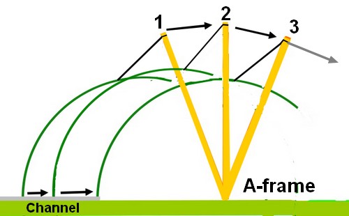
The present, inverted orientation of the [three + 1 spare top section] nested segments is not at all helpful. Righting them into a proper, hemispherical dome will require some ingenuity. The individual segments are far too heavy to handle alone. [70kg/180lbs] 

I have now deleted the long-winded discussion on how to remove of segments from the trolley. First I used the boat winch to pull the trolley towards the edge of the parking space. Which allowed me to drive the car and trailer out. I fetched some more 2x4s and coach bolts from the builders merchants. This gave me time to rethink the problem concerning the trolley.

If a pair of strong young blokes can handle the segments. Then so can a strong and determined old fool like myself. 

So I took the wheels off one side of the trolley to tip it downwards. Leaning towards the target landing area. Then I slid each segment gently forwards. Until they could be tipped onto their lower edges on scraps of protective board. 

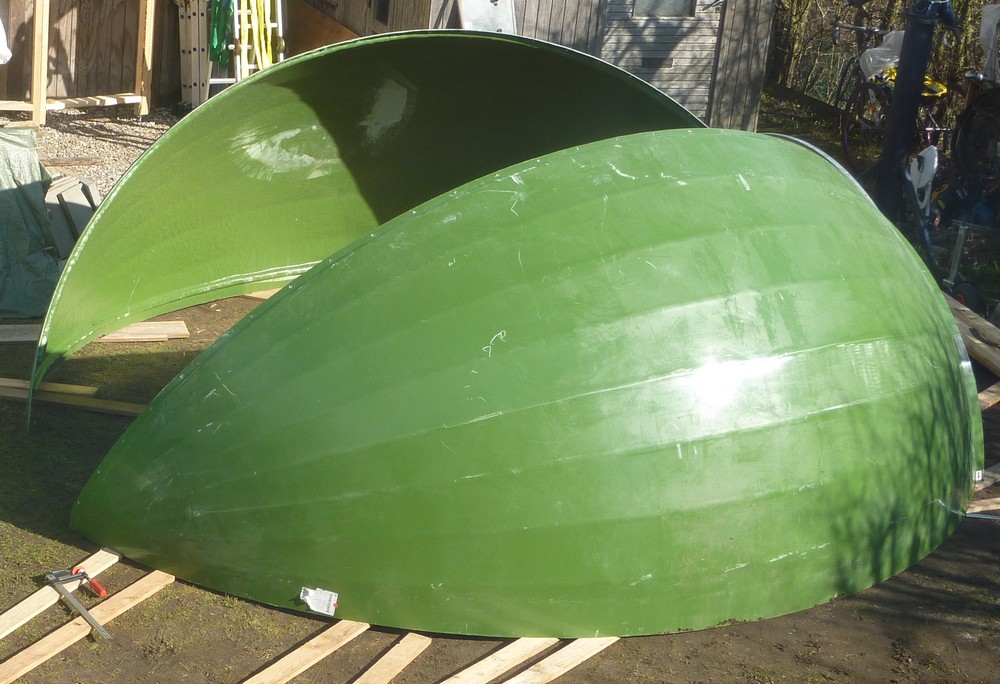
By standing at the pointed end I could safely control them as each segment was gently flopped "upright." Once they were standing on one, curved edge I could walk the segments forwards. Though with great difficulty. That said, they are now much more manageable than lying on their backs as rain collectors! The last, base segment still needs to be raised in the first two images. It being the lowest in the stack on the trolley. It did not enjoy the same degree of tipping over the edge of the trolley. I had to use rather more effort to get it safely up on its base edge.

The large "targets" on the [typically rough] GRP inside surfaces are water marks. From where the segments had been stored outdoors facing the sky. Presumably for quite some time. Meanwhile, the shiny outer sides are far more scuffed than I would like. Though some minor scratches responded to a rub with my glove. I believe that Gel coat restorers are available.

I do appreciate that these things are intended as agricultural buildings, but still. Removing them from the lorry using a fork lift truck would have been preferable. I just didn't have one available. 

The crane and lifting strops allowed the segments to slip and rub against each other. Causing the scratches. Having to shed the huge volume of HEAVY water, which had collected between them, did not help!

The cleverly moulded, external facets alter the the light and colour in a pleasing way. This will help to disguise its presence in the rural scene once installed on the enlarged building. The finish is claimed to be thermally reflective. After several hours of sunshine in 45F ambient the GRP still felt cold to the touch. Not truly indicative of likely summer conditions but certainly positive. I was certainly warm myself while working in the bright sunshine all afternoon. Spent completely dismantling the trolley and struggling to move segments. 

I have now reversed the second base segment's orientation. It needs to take the place of the other one in the now, very crowded, parking space. This will allow one of the roof segment to be fitted between them. I shall practice moving the segments on boards tomorrow. Dragging them across the bare ground is very hard work. I tried using a sack truck but it didn't help. The ground is just too uneven and the segments far too large and heavy. 

I'd suggest having at least three strong adults present if you are tempted to assemble this 14' calf dome. The problem is finding somewhere for more than two people to grasp the segments. You can only have one worker at each end. The middle top it far too high to reach! Lifting it off the ground to find room for more hands under the lower edge takes serious muscle power. Using grippy rubber gloves on the usefully textured GRP I can barely lift one end clear of the ground! Who are you calling a wimp? 😎

The segments measure 210cm maximum width. [Ignoring the different edges and overlapping joints.] The sagitta, below a straight edge bridging the opposite sides, is about 30cm. Which can hold a huge volume of rainwater! Along the curved length is 5.2m. Only 4.3 meters, in a straight line, from the curved doorway to the pointed end.  

I measured a maximum of 4.2m from the doorway to the 1m wide point. To provide the 2x 50cm wide shutter material. The 1/6 "equator" is 2.2m wide at its widest on the roof sections. This includes an overlap on both, long sides of course. All measurements are approximate due to the top/roof section having two external overlaps. 

Both base segments [handed] L&R have one solid edge where they meet the ground. and one internally overlapping edge. Forming a sort of halving joint with the roof. With the top/roof section[naturally]  overlapping both base sides to shed the rain. I haven't measured the joint widths yet. It was already dark when I realised I had no numbers to play with. So I nipped out with a torch and a fibreglass tape.

A roll of soft, malleable tape is provided to ensure weather tightness at the joints. The supplied roll was in a canvas bag. Along with the short, coach bolts and everything was literally sopping wet from the recent rain. I am allowing it to dry naturally to see if the sealant can still be used. Any hint of adhesive properties is presently, totally absent. The sheer number and weight of the sturdy, galvanized, coach bolts and matching nuts is difficult to believe. 

A PDF file of the assembly instructions was provided by the dealer on acceptance of my order.

*

15.3.21

15.03.2021 Big dome day! What a disaster!

 *

Monday 15th 39F, heavy overcast. The dome delivery is due this morning. Having been put off from Friday due to bad weather with gales. 

Will the huge trolley live up to expectations? Can it cope with a 300kg load spread across its back? I really have no idea. The weekend was spent making it stronger and safer. It hardly flinches to my modest weight now. 

What if the delivery driver decides he doesn't like the risk? The dome "kit" will have to go on the grass 120m from its intended target in my garden. 

I plan to screw plywood offcuts and boards to the top surface to spread the load [even] more evenly. I'll get on with that immediately after breakfast. 

I laid the plywood template arcs on the trolley to get a true idea of the support required. Whether the segments will fit inside the wheel jacks on the right remains to be seen. See image. I have lowered the jacks so that the wheels just clear the rails. This might help to improve stability and reduce the "leverage" on the jacks. The rear wheels will be locked straight ahead for more sensible steering. I had a test run towing the trolley with a lifting strop and it went well. Though it is far heavier than when I started.

The van and trailer turned up just after 2pm. The segments were lying on their backs like nested, rather elegant boats. Except that most of the water was inside the boats! As the load was lifted by the crane it tipped lengthways and water gushed out! Many cubic feet of it!

My trolley didn't like the heavy load! Such that one long, side rail rolled inwards. Bending five 12mm coach bolts holding it to the cross bars. The same rail which was holding two sets of wheels.

It took over an hour just to move the trolley off the main drive. I was using the car to tow it along at a snail's pace. Then another hour to get it to the gate. Then more time to reach the parking area. The wheels kept flopping over sideways on the jacks. So I reversed the clamps to make the twisted timber work for me. It didn't help very much and had to be corrected each time. Using wooden blocks and a length of 2x4 as a lever. Just to stop the wheels dragging sideways through the gravel. Of course it rained almost non-stop from beginning to end of the whole, sorry farce. 

The segments look rather scuffed up but will no doubt respond to a specialist GRP polish. Tomorrow promises wall to wall sunshine! I already know how I intend to roll the segments upright. Using an anchor post and my secondhand boat winch. Did I mention how pleased I am with the dome parts and the sheer scale is absolutely mind blowing? The BBC calls my lifelong affliction "toxic positivity." 😋

*

14.3.21

14.03.2021 Trolley mods.

 *

Sunday 14th 36F, dry, bright start with light winds. Variable cloud and even some light showers during the day.

The trolley has taken up my time when I could have continued work on the building. Lots more cross bracing to do but no 2x4 timber left to cut any.  All the long lengths went into the trolley. I may add the [missing] joist extensions to pick up the [missing] cross braces. 

I wonder if I have any suitable bolts? The builders merchants are closed on Sundays. Though I could cycle the ten miles to town and buy the bolts from the discount, DIY, big shed chain. They shouldn't add too much weight for the journey back. 

I found some 12mm galvanized, threaded rod. [studding] So I replaced all the over-long screws on the trolley's jack clamps. I used a socket wrench to tighten the nuts really well. The timber offcuts, in the car trailer, were tidied into boxes in the shed. To make the trailer useful again.

*

13.3.21

13.03.2021 Trolley reinforcement.

 *

Saturday 13th 39F, heavy overcast and all day rain. 

I am trying hard to avoid a trip to the builder's merchants. So I placed some very large roofing washers under the nuts holding the jockey wheel clamps in place. This stiffened everything up quite nicely. The jacks no longer twisted away from the offset wheels. Without supporting washers the nuts had pulled into the softwood timber. Making the fixings loose.

There are some some odd, long lengths of board in my stock. Sadly they aren't thick enough to usefully reinforce the 4m rails. I might screw these across the trolley bed to spread the loads on the segment edges more evenly. Scraps of cladding plywood could be used to much the same effect. I'll have to see what else was hidden away in dark corners of the shed during the last observatory build. A few odds and ends will all help. 

11.00 I have just emptied the rain collection trays in the dome. The rain is pouring down indie and outside now! 

Afternoon: I decided to sacrifice two long lengths of larch flooring [125x32mm] to reinforce the lengthways trolley rails. There was a struggle to find suitable bolts to hold the wheel clamps in place. Most of my stock of coach bolts were too long or too short. Then I had to open up the holes in the clamps to 12mm. The trolley feels much more solid now. As do the wheel jacks in their clamps. I have moved the clamps to the inside of the frame to reduce the track.

*