28.9.18

Octagon doors and more dome work.

 *

Thursday: I worked on both sets of doors. They still all need trimming with a plane on the hinge sides to make them match in the middle. The upstairs doors to the veranda open outwards. The main doors on the ground floor open inwards.

Had the main doors opened outwards they would have caught the wind and caused damage to themselves or myself. Now they fold back. Well out of the way to allow me to carry bulky objects inside. I shall have to find a lever door handle to do them proper justice. Before I hung the main doors there was a gale blowing up through the open pier. With the doors closed it had gone.

Friday: Worked on the main doors, the shutters, the top tier of panels and sanded the panel sealer. I produced about a pint of dust and shavings of sealer working high up on the ladder. I didn't count how much dust went inside me. Ordered two more cartridges of sealer. A  breezy but mostly sunny day with a max of 57F.

At dusk I decided to cover the shutters independently with the clear, net reinforced tarpaulin. I can't believe it has taken me this long to discover the ease with which this can be done compared with covering both doors at once. With the shutter doors open I have full access from top to bottom from the internal stepladders. Bung a few spring clamps on the outside edges and trap the inside edges between the doors as they are closed. Job done.

The 5' lengths of 4mm ply which I had been carefully savings for the shutters proved to be an inch too narrow! I shall now have to buy even more 4mm birch ply. I can get only three lengths from a 5'x5' sheet but need four. Then there's the ply strips needed for lowering the skirt. Perhaps ten strips from a full sheet. I can use some of the undersized strips to save waste.

I wielded my ancient "Sheffield made" tin snips to see if I could cut a straight line at 80° on the Z-profile flashing to extend the skirt.  It didn't go badly at all but needed tidying on the front drip nose where they meet. This flashing is not a simple pair of right angles. The whole profile deliberately slopes for drainage. Cutting across the angles takes care not to distort the metal.

So I resharpened the hardened jaws on the tin snips and beat the rivet to tighten the joint slightly. Then I was able to cut along parallel lines only 1/16" from the last, right to the very tip of the jaws.  I'm still thinking about how to deal with the lower drip nose. It might be worth cutting away some of the return fold underneath to allow the edges to meet more neatly. The image shows my first attempt. Eventually the edges met over their entire length. If I'm cutting them simultaneously to length then I don't have the luxury of re-cutting them. They have to be exactly the correct length and correct angles to meet at each corner, or not at all.

Click on any image for an enlargement.
*

25.9.18

Dome build: Lowering the hemline.

*

I have discovered there are much wider versions of my plastic DPC roll which I used as a mini skirt on the dome's bare midriff. 30cm would be more than enough. Then my wife suggested I cut strips from some heavy, rubber pond liner. This would be much stiffer and heavier than the thin plastic strip.

Which would help to keep it in place compared with the plastic. Which blows inwards far too easily in windy weather. Being much too short does not help because there is nothing to resist it. First I need to add some heavy sloping mouldings to the bottom of the dome to push the skirt out to clear the octagon top ring. This would reduce potential friction issues with the skirt on the roller brackets. Though quite what it will look like is another matter!

If full clearance is achieved then plywood could be substituted for the softer 'curtains.' An earlier plan was to have an upstand to foil the wind leaking under the skirt. This would be critically dependent on avoiding water ingress.

An alternative would be to use aluminium  windowsill flashings. These are available in considerable depths. Though 90mm seems about the maximum off the shelf from local DIY outlets.

Aluminium flashings are lightweight, long lived and weatherproof compared to diagonally ripped 2x4s on the table saw. The short upstands could be tucked under the bottom of the ply cladding for perfect drainage. But how would I cut them on the diagonal? You can't just go at them with a pair of metal shears because of all the angles. They'd need to be cut on the diagonal to match the next one along. Plus a suitable tab on the edge for pop riveting the sloping joints together.

I was given some joining plates too which might be useful. The pond liner, rubber skirt would hang down from the underside of the bottom of the profile. Probably using washers to spread the loads on the pop-rivet fixings. Though nuts and bolts would offer greater control. I'd have an outward gain in footprint of about 90mm. That's 3.5" increase in radius or 7" on diameter. The present, plastic skirt drags on the roller bases in places. So freeing them up should improve rotation.

I chose a fine toothed, arc-shaped blade for my DeWalt multi-cutter to cut the diagonals on the flashings. I now have 16 x 1m long flashings and must measure the angles required. Though not immediately as it is blowing a gale all day today.

From my computer desk I have been watching the tarpaulin which I spring clamped over both shutters. Removing hundreds more staples didn't appeal. First it rose at the top and then became more baggy lower down as the day wore on. After earlier lifting I faced it directly into the wind and this seemed to work best. It lifts, but then falls straight back into place. There are only light showers so I'll leave it to do what it will.

The mounting is well covered inside the dome. If the dome was better sealed around the base the shutter tarpaulin might not lift so readily. It could be internal inflation or it could be aerodynamic lift over the dome. At least the veranda doors are keeping some of the wind out. I also bought some sturdy bolts to keep them shut.

Today's wind and afternoon rain had a much lower impact than past episodes. The observatory floor was completely dry, but then, there was no cloudburst today.  If I can solve the problem of sealing the joints properly it could be worth continuing. After carving the joints flat I shall have to be sure they are completely dry before applying more sealant and trying to work it in. The Sikaflex 291/591really doesn't like filling its own holes.

Meanwhile I can get on with extending the skirt. Ideally I need a jig to guide the saw diagonally across the flashings. Not easily done with a Z-shaped folded length of thin metal.


Click on any image for an enlargement.
*

24.9.18

Dome build: Veranda doors.

 *

Monday: In the morning I drove to buy some galvanized T-hinges, some latches and another sheet of grooved, plywood for the observatory doors.  Fortunately I had a choice of big shed DIY outlet and selected the best options on offer from each.

During the afternoon I fitted the upstairs, double doors out to the veranda. Not enough time to fit the latch to hold them closed. I'm using the same 1/2" [12mm[ grooved plywood as the rest of the building for uniformity. It is a matter of personal taste whether you like this material. I do, and it's my building project. It is commonly used for garden sheds and cladding carports and garages. Mine are still bare ply at the moment but I shall add thin frames to the insides. Hoping to prevent them warping over time.

I also hope to avoid adding any [weather] framing above [or below the doors] because it would impede my ducking under the octagon top rail. The door height is a smidgen over 135cm. Or just over 4'5" in Olde Money.  Having ducked under the bar literally hundreds of times during the build I don't find it too onerous.

Though I should emphasize that I would not want it to be the main point of access. I have a habit of losing concentration while thinking furiously about something else and then hitting my head. Which is why I usually wear a hat while working on the observatory. 

It was quite a hard decision deciding where exactly to place the hinges on the octagon posts. There seemed to be too many options. I finally settled for a well recessed position on the inward slopes. This provided plenty of overhang above to reduce the impact of wind driven rain. The veranda doors face west towards the prevailing wind and rain.

The doors had to open outwards since the ladder handrails bump against the doors in their closed position. Quite deliberately I might add. There is just room to push past the open doors when walking along the 60cm wide veranda. The doors each ended up 52cm wide for 104cm in total. About 3'5". 


Click on any image for an enlargement.
*

23.9.18

Dome build: Shutter adjustment.


The leaky dome roof is very depressing. Five tubes of marine sealant consumed and it still leaks like a sieve! I have started having repetitive dreams about taping the seams, fiber-glassing and cladding the dome in heat welded tarpaulin. Shrink wrapping plastic doesn't last long enough to be worth the expense and effort. Only shrink wrapping would keep the facets crisp.

The afternoon was spent correcting the shutters. First I lined up the outside edge of all four ribs. That meant a 2" outward movement for the inner ribs. Then I reset the height so all were level on top. I discovered that non-parallelism made the slides "sticky" at the far end of the shutters.

Careful examination from above showed that the inner slides were being pulled, or pushed, inwards or outwards at only one end. This was due to the timber to which they were screwed being skewed by the misaligned ribs.

I replaced the original [roofing] battens with 2x4s to have more meat to screw into. Then I had to trim back the ribs up at the top to clear the zenith board. Then all the slide screws had to be replaced because the originals would not run through the slides without the oversized heads hitting them. Ironically they could cope with the big screws when incorrectly aligned.

Eventually the shutters could be closed, or opened effortlessly, from anywhere along their length. A frustrating but still interesting exercise involving endless ladder climbing. In retrospect I could have left the ribs untrimmed but thought I had no choice at the time. When I first fitted them the ribs were stretched tightly between the slides. With no way to free them except to trim them back on the inside.

Monday: A drive to collect some galvanized T-hinges, some latches and another sheet of grooved, plywood for the observatory doors. During the afternoon I fitted the upstairs, double doors out to the veranda. Except for the latch to hold them closed. I'm using the same 1/2" [12mm[ grooved plywood as the rest of the building. Still bare ply at the moment but I shall add thin frames to the insides to prevent them warping over time.

I hope to avoid adding any [weather] framing above or below the doors because it would impede my ducking under the octagon top rail. The door height is 135cm. Just over 4'5". Having ducked under the bar literally hundreds of times during the build I don't find it too onerous. Though I would not want it being the main point of access. I have a habit of losing concentration and hitting my head. Which is why I usually wear a hat while working on the observatory. 

It was quite a hard decision deciding where to place the hinges on the octagon posts. There seemed to be too many options. I finally settled for a recessed position on the inward slopes. This provided plenty of overhang above to reduce the impact of wind driven rain. The veranda doors face west towards the prevailing wind and winter rains. The doors had to open outwards since the ladder handrails bump against the doors in their closed position. Quite deliberately I might add. There is just room to push past the open doors when walking along the 60cm wide veranda. The doors each ended up 52cm wide. 

I have discovered there are much wider versions of my plastic DPC roll which I used as a mini skirt on the bare midriff. 30cm would be more than enough. Then my wife suggested I cut strips from some heavy, rubber pond liner. This would be much stiffer and heavier than the thin plastic strip. Which would help to keep it in place compared with the plastic. Which blows inwards far too easily in windy weather. Being much too short does not help. First I need to add some heavy sloping mouldings to push the skirt out to clear the octagon top ring. This would reduce potential friction issues with the skirt on the roller brackets.


Click on any image for an enlargement.
*

22.9.18

Dome build: Doors, trapdoor and foot stop.

*

Saturday: Yesterday's "storm" was a bit of a damp squib locally but a valuable warning. It was no problem leaving open doorways during the summer but this will have to change if we get wind driven snow. I shall just have to build some weatherproof doors using the same grooved plywood as the octagon.

Both would have to be double doors to be manageable. The veranda door cannot open far if it is not made double. A single main entrance door could easily become uncontrollable in typical windy conditions in such a large size. It is just short of a full 4x8' sheet unless I frame it down to a more normal size. A large door is handy for bringing telescopes in and out. Though this is likely to be an increasingly rare occurrence once I'm set up.

After endless consideration I decided that I would not move the veranda door from the top of the internal ladder. Nor did the double doors need to pass over the top of the trapdoor when it was lying flat on the veranda. The doors would always need to be open to lower the trapdoor outside. The trapdoor will ensure the doors are not closed by the wind.

However, the doors need not be open for the trapdoor to stand vertical. I shall add a couple of small, door bolts to ensure the heavy trapdoor stays upright when needed.

I finally added a length of scrap, alu. angle to act as a foot stop [bumper?] near the end of the closed trapdoor.

The image shows the view over the closed trapdoor from the veranda. Into the pier and across the open gap to the eastern observatory floor. The foot stop is level with the outside of the pier legs where they pass through the obs. floor. This just seemed to be the logical position to have them. Since it continues the natural foot stop provided by the pier cladding on the other three sides. The clearance around the isolated pier is well seen on the far left, 4'x4' leg.

Those who have been paying attention will remember that I climb up the stepladder. Through the hollow, pyramidal pier. To reach the observatory floor, 10' above the ground.

When the trapdoor is lowered flat onto the veranda the alu. angle passes cleanly between the deliberately spaced, larch floor boards. This avoids the trapdoor being propped up unnecessarily. I also avoids damage to the veranda floor by the foot stop. A happy coincidence thanks to careful marking out before the foot stop was screwed down onto the larch trapdoor.

The leaky dome roof is very depressing. Five tubes of marine sealant consumed and it still leaks like a sieve! I have started having repetitive dreams about taping the seams, fiber-glassing and cladding the dome in heat welded tarpaulin. Shrink wrapping plastic doesn't last long enough to be worth the expense and effort. Only shrink wrapping would keep the facets crisp.

The afternoon was spent correcting the shutters. First I lined up the outside edge of all four ribs. That meant a 2" outward movement for the inner ribs. Then I reset the height so all were level on top. I discovered that non-parallelism made the slides "sticky" at the far end of the shutters.

Careful examination on top showed that the inner slides were being pulled, or pushed, inwards or outwards at only one end. I replaced the original [roofing] battens with 2x4s to have more meat to screw into. Then I had to trim back the ribs up at the top to clear the zenith board. Then all the screws had to be replaced because the originals would not run through the slides without the oversized heads hitting them.

Eventually the shutters could be closed, or opened effortlessly, from anywhere along their length. A frustrating but still interesting exercise involving endless ladder climbing. In retrospect I could have left the ribs untrimmed but thought I had no choice at the time. When I first fitted them the ribs were stretched tightly between the slides. With no way to free them except to trim them back on the inside.


Click on any image for an enlargement.
*

21.9.18

Dome build: A bit of a storm in a bucket.

 *

I have invested in a safety sling to use as a climbing belt. My multiple strands of rope belt was clumsy and uncomfortable. The sling needed a figure-of-eight knot to use up some slack but was fine after that. I put a caribener through both ends of the loop and clip my scaffolder's hook and tether onto that.

A great improvement on the rope but certainly not worthy of serious, professional use or rock climbing. I have no plans to fall more than a foot and am being extremely careful at all times. It just provides me with slightly more confidence when I am working right at the top of the ladder. I clip onto the top rung to limit any fall to an absolute minimum. My head is rarely above the top of the ladder and the tether kept short and taut.

Friday and it is already windy with showers promised. The gale forecast has dropped to 20m/s or 45mph gusts on a 12m/s or 25mph base. I have to cover the door openings with ply to stop the dome inflating and pushing off the shutter cover. I didn't want to cover the shutters individually because of the rain running between them.

BTW: Never trust tarpaulins to be remotely to the stated dimensions. There is a Chinese billionaire banking on your not measuring his ephemeral wares with a tape measure. My 3x4m tarpaulin was 10cm or 4" short of any consumer law worth the virtual paper it is written on. Ironically I needed exactly 3m to fit the shutters. So I had to cut it from the 4m length.

I also covered the veranda doorway and the main entrance with stapled, reinforced PE. I had to fix them on the inside so I could escape. So I added some crossbars to stop them blowing in during the storm.

Just for the fun of it I hung a 1lb weight on a thin cord from the obs. floor to see if the building was moving. Since it was so windy I hung the weight in an empty bucket to protect it from direct external influence. A real pedant perfectionist might have added damping fluid too but I forewent that finer detail.

The problem with this experiment is finding the resonant frequency of the building and matching the pendulum length [and therefore its period] for maximum sensitivity. I was limited by the presence of the ground but had no immediate plans to dig a deep hole for the bucket. Conversely I might have tried shortening the pendulum but that would have meant finding something on which to place the bucket.

It now occurs to me that I could monitor the building's longer term behaviour with a pointed plum bob over something immovable like a large nail point protruding from the gravel floor. There are plenty of non-trafficked areas to set this up. Any relative movement would suggest subsidence.

In the time since the building and pier have been standing I have only once felt the need to adjust the pier jacks for increased clearance from the observatory floor. This amounted to only 1/4" at 10' above the ground. So was hardly dramatic.

Click on any image for an enlargement.

*

20.9.18

Dome build: Reinforcement.

*

Wednesday: Spent the day fitting top tier, vertical bracing battens. Compound, undercut miters needed care to avoid a sloppy fit. Which would rather undermine the whole point of fitting them. It took several journeys up and down the ladders to trim on the miter saw for each batten. I am paying dearly in wasted time for the dome being 'upstairs.' Had it been down on the ground it would have been far quicker. But then the finished dome would still need to be lifted up onto the rollers to within an inch or two, in 3 planes, by a complete novice at driving a telescopic loader. I wasn't willing to take that risk.

Another risk is high winds. Tomorrow promises westerly, 50mph gusts. The first real gales since I built the observatory. Fortunately there is a shelter belt of trees to the east. Though it isn't very deep it does provide some protection.

Now I am wondering if I should hastily provide a guy-line cable, or two, connected to buried concrete anchors. Precast carport anchors could be reinforced with large concrete slabs to increase their surface area against soil lift. This would offer increased resistance if needed. There is nothing westwards of the building to prevent such digging. I am suddenly aware of the rather small footprint of the octagon. It has proved remarkably stable until now. With no obvious change in level. Dare I take a risk and do nothing? Or use the time to provide some defense?

I decided against the guy-lines for the building itself. But I added four ratchet straps between the dome zenith and the pier. If the pier decides to lift, despite the hold down disks then the straps should add further restraint. The pier is massive as is the mounting on top of it. If the pier lifts then so must four more, buried,  precast concrete anchors.

The forecast is gently lowering toward 20m/s which is about 45mph. It will be an interesting test. The panel sealing is proving almost worthless. With the interior of the dome showing wet patches from rain water draining down the inside. It starts at the bottom of the top tier so I shall have to concentrate on that area with more sealant.

I fitted some net-reinforced, clear poly tarpaulin over the closed shutters to let the light in and keep the rain out. Whether it survives tomorrow's gales is quite another matter. Reaching anywhere near the top of the slit to staple the PE was completely impossible. I'm not sure what the answer is to the poor zenith access when the shutters are closed. A rope ladder? I could rejig the added top ladder. Pull out the base of the ladder to lower the angle at the top. The problem then is rotating the dome. The shutters will strike the ladder. A folding [builder's] stepladder could be cranked over the top of the dome. That would need serious support and bracing! Just getting the ladder up there would be difficult.

The dome is not strong enough locally to support separate roof rungs designed for chimney sweeping access. Once the shutters are functional and covered, the access problem goes away. That is, until I take away the tall stepladders.

It was suggested I arrange a strong support at the zenith. To allow a hoist to remove the heavy mounting. A thick wall pipe could pass right through the ribs and the shutters without affecting the weatherproofing. Water pipe with flanges bolted to the slit ribs? That would save having somebody else fabricate something with welding. Though a pipe might block the sky slightly more than  a steel strap. The steel strap would have the advantage of reinforcing the spacing of the top of the ribs. It would also tie in the zenith board of the observation slit. 


Click on any image for a enlargement.

*

17.9.18

Dome build: Skeletal shutters fitted.

 *

Monday: Trimmed notches on the insides of the [central] shutter ribs, top and bottom [for hours!] just to clear the slides.  I do now have the ribs closer to the dome but it's still not optimal. Paused for lunch to think about it. Perhaps making new ribs to longer radii is the answer?

Further notching of the ribs [for more hours!] finally achieved clearance. I could now screw the shutters to the slides. They proved so free moving that they moved in the wind while I was taking photographs from down on the ground.

The shutters are not very straight and the cross-braces are all over the place. No point in doing much more than this until it was proven they would work. They will have to come back down to be straightened and covered in ply for stiffness. They are sagging and wobbly in their present, skeletal form.

Screwing the slides to the shutters was easy at the top because they were fully exposed when open. At the bottom I was just able to get the drill/screwdriver in between the dome and the shutter when I pulled the slide fully out. Otherwise it would not have been possible because of the woodwork getting in the way.

I lost one shutter to the wind this morning as it slid off the dome at the top and crashed down onto the veranda! Fortunately there was no damage, except to my pride. More aches and pains after another days of endlessly climbing ladders. You would not believe how many times I have to climb up and down in a day.

Take my advice and build your own dome on FLAT ground. Preferably a flat floor with a secure roof over it! So you don't have to collect every tool and drag tarpaulins over everything at the end of another exhausting day. The cost of a hired lift cannot compare to the wasted man hours just going up and down ladders!

Tuesday: Warm and very windy. I spent some time fitting new battens to the shutters. More time opening out and sealing between the panels. I need to cover the shutters to keep the rain out, instead of using worn out lightweight tarpaulins. The roughness of the dome is really taking its toll.

My wife suggested polythene on the shutters for its clarity and waterproofing. This would allow natural light in instead of making the dome very dark inside. I still have some DPM film which is quite heavy.

The images show the compound tilt on some of the shutter battens. I think the top slides need to be raised at their outer ends. That will flatten the top battens. Not sure about the lower battens which are pointing inwards. Both ends are flush with the outer edges of identical ribs. I'll try pushing the bottom slides outwards at the center.

Click on any image for an enlargement.
*

Dome build: Shutters: Scaffolding, slides and shutters.

*

Scaffolding:
I spent some time providing 2x4" notched "legs" for the horizontal bracing ladder. This will allow me to stand on the thick plywood laid on top of the ladder. Giving me much better access to the outside of the dome. Standing on the big outside ladder pushes me out too far. So I have to stretch just to touch the dome.

I also fitted the lower slides to the 2x8 across the bottom of the observation slit. Just to get a feel for how the shutters will attach. The support member[s] for the slides will need to be midway between the front and back of the shutter.

Shutter skeletons in place to check clearances. I can't rotate the dome at this point because the shutters are resting on the board on top of the horizontal ladder.

I now plan to add the slides to the shutter doors last. I just need to prop them, from the bracing ladder surface, to take their weight. Then reach inside the shutters from within the dome to put the fixing screws through the extended slides. If I can't reach easily I shall just have to remove the two lower panels from the dome on either side of the slit for easy access.

It's odd how new ideas pop up from making simple changes elsewhere. The braced ladder, now acting as firm scaffolding, opens up new possibilities. I have fitted the U-section of the ladder side rail around the octagon base ring timber with lots of long screws for security. So it can't rise or fall out of position and the big outside ladder is already forcing it inwards. With the screws providing extra security.

Shutter drawer slides:

I took the outer ribs down and fitted the top slides. Then I quickly threw the shutters together. Since they will be plywood clad from existing 4mm sheets I don't really know where to put the crossbars yet.

I was struggling to make any sense of the obstructions at top and bottom after I carried both shutters up bodily, in a gale and plopped them over the dome. I can only assume that the inner  ribs of bi-parting shutters have to be notched to clear the slides. Nothing else makes much sense unless the slides are fitted literally underneath the doors. My slides are about 10" above the present bottoms of the doors but very close to the ends of the ribs at the top. As it stands my doors won't snuggle down against the dome because both sets of slides are literally getting in the way.

I've done an online search for domed observatories and it seems some people make the inner ribs much narrower than mine. I think I'll try notching around the drawer slides first. Though narrower ribs would certainly be lighter they would also be weaker.

It is possible I may have made an error on the radii of the shutter ribs. I cut them to 150cm and 165cm inside and outside radii because I thought they'd sit much lower on the dome. Because the slides are pushing the ribs out more than  expected, this exaggerates the error. If I can get them nearer the dome the problem [largely] goes away.  I could re-cut the inner radius larger to match their final situation. Making new shutter ribs means another £40 equivalent in materials alone and hours of work. I'd rather solve the problem by lowering the shutter ribs closer to the dome.

I had my first experience of the dome in darkness as I covered it over for the forecast, overnight rain. Sadly the sky was clouded over so there were no revelatory moments. The Moon would have been well placed clear above the house. The previous night it had been completely invisible from the garden below. But easily seen from the observatory floor.

The observing slit seemed much narrower after the shutter skeletons went on. The shutter ribs seem to block the sky. While the half width doors seemed strangely narrow with the middle ribs in place. I am used to standing well out of the observing slit to haul the tarpaulins up off the veranda floor at the back of the dome with a rope. This will change when I can open the shutters. Hopefully tomorrow. All this will change again when the big stepladders and their ratchet strap guy-lines have gone. Leaving the dome empty but for the big mounting on its pier. I shall probably go on ducking for months after that even when the ladders have long gone.

Monday: Trimmed notches on the insides of the [central] shutter ribs, top and bottom, to clear the slides.  I do now have the ribs closer to the dome but it's still not optimal. Paused for lunch to think about it. Perhaps making new ribs to longer radii is the answer.


Click on any image for an enlargement.

*

16.9.18

Dome build: Shutters: Mounting the shutters?

*

Planning meeting of one: More inner contemplation. Move along please! Nothing to see here.

Having the central ribs ready means I have to mount them on the dome somehow. Which means I have to make a decision on where to do it. Down on the ground? Or up on the dome? Bringing the outer ribs down means I can build the shutter frames quickly and easily. Then each shutter can go back upstairs. Here lies the next problem.

Building the shutters up on the dome means struggling for access. While the outside ladder may lean towards the dome it feels decidedly unsafe despite my scaffolder's hook and safety line. The ladder really only offers safe access to the lower sections of the dome.

Access from the slit via the internal stepladders is highly rotation dependent. The problem is always one of not being able to rotate the dome because it then denies me access from the outside ladder. I usually need both sets of ladders to reach the dome with new build components. You will just have to imagine the endless descending and climbing during a day's work.

Lifting the finished shutter frames must be done from outside. They must have something to hook onto at the top of the dome for safety. Not only are they quite heavy but they are large, very cumbersome and vulnerable to wind gusts. The shutter's curvature makes it a difficult lift up a high ladder. 

I only have one pair of hands and normally need at least one to hold onto the ladder. A winch doesn't really help because of the oddly shaped load and the ladders, shed roof and veranda getting in the way. Besides, there is no gin pole with a pulley sticking out of the dome. And if there were it wouldn't help much. There are simply far too many hurdles on the climb.

Which leaves me with the option of adding central ribs to the existing outer pair. But how? The crossbars holding the outer ribs will have to be removed. Sky hooks are in relative short supply locally.

I could temporarily screw the outer shutter ribs to the slit ribs before removal of the long crossbars. The central crossbars can be braced to sit side by side in the middle of the slit to match the outer crossbars [temporarily fixed] inner position. Then the short crossbars can be added between the two sets of ribs. Now they are shutter frames I must add the drawer slides. The slides go where the shutter frames are presently hanging.


Click on any image for an enlargement.

*

Dome build: Shutters: More shutter ribs.

*
I need to decide what to mount at the top of the slit to take the heavy drawer slides. There is presently very little room above the top tier of panels at the top/back of the slit. So I shall have to sandwich some thick plywood tall enough to take the slides. Failing that I might have to cut the panels back to allow a taller plywood plate across the full width of the slit. Or replace the present one with something taller and thicker. That would save me losing some of the opening beyond the zenith.

This plate will have to be strong and well attached. Not just to carry the weight of the shutters but to cope with the inevitable drag from gales plus potentially heavy snow loads. A couple of 15mm birch plywood strips laminated together should do. Though three layers, to achieve odd numbers of veneers, might be preferable. 3x12mm? I could bolt on some serious, roofing angle brackets for a better fix to the observation slit ribs.Then there is always 10mm aluminium for a top crossbar to carry the slides. Would it become a lightning conductor? Not likely when there are more metal domes than wooden ones.

I was just removing the zenith board when there was a heavy shower. So I scrambled to cover the slit with a smaller tarpaulin. I need another 55mm of height on this board for the top, drawer slides. Though I really don't think it needs to be quite so massive as I suggested above.

I didn't have any aluminium wide enough so used 18mm birch ply instead. It is further reinforced by a curved strip of 15mm ply which supports the top tier of panels.

I bent some rectangular roofing plates to 90° and screwed those to the corners between the top board and obs. slit ribs. I also made the central shutter ribs and placed them in the shed for safety from the frequent showers.

The ladder was obstructing the shutter when the dome was turned. So I reset the big ladder to its original slope and re-fixed the near horizontal bracing ladder.

Making a skirt for the dome will be more difficult than expected. When I stapled some wide DPC to the bottom of the dome it dragged on the support wheels. Though it did look acceptably smart as a temporary measure it needs to be further out. Perhaps a wide moulding with a sloping top produced on the table saw? It would be attached at the bottom of the dome to give it a wider footprint.

The difference in diameter between the dome and octagon was due to the change to a 16 sided dome. A round dome cleared the octagon but the flats of the 16 sided one fell just inside the top, outer "corners" of the octagonal building's top ring. I can't cut off the corners because this is where all the rotation rollers support brackets lie. A wider dome base ring would help but would collect rain.

Yesterday evening I was using a router trimming bit to match the central shutter ribs. The shavings were flying up in the air like a fountain! I am aching all over today after my recent activities. There was a lot of lifting and climbing involved and it went on for hours. My back, hands and elbows are aching from the constant physical demands being placed on them over the last year or probably two. My left hand has been feeling 'sprained' for ages. It is actually a struggle to unscrew the top of the toothpaste these days.


Click on any image for an enlargement.
*

14.9.18

Dome build: Shutters: Lifting and fitting the outer ribs.

 *

Friday: Bright start but risk of showers. Getting the spaced pair of shutter ribs up the ladder was a real struggle. The bottom crossbar kept hooking under the second ladder. Then it all blew sideways as the gusty wind really picked up.

That actually helped because I needed the rib assembly to slide inside the top of the outside ladder. In the end I had to add another crossbar midway. Then lift and re-screw the top crossbar repeatedly to allow the shutter ribs to sink down to the dome surface. Which meant my plywood reinforcing patches were now in the way.

Another crossbar was needed to tie off the ribs to the top of the outside ladder with the ribs tipped well outwards. Just so I could rout the patches away to clear the slit ribs. All the while dangling off assorted ladders with squally, light showers @ 59F passing through.

Stopped for lunch at 2pm with routing to follow. No chance. As soon as I climbed up to the dome it started raining hard. The tarpaulins would not pull up over the dome because they were wet and the friction was too high on the slightly roughened surface. So everything is thoroughly soaked and I needed a complete change of clothes. The temperature has dropped to 56F.

At least the shutter ribs are proving to be about the correct length. With overlap above and below the dome.

Later in the afternoon, under a grey and threatening sky, I completed the routing of the oversized plywood patches. I simply screwed a curved scrap of plywood rib above the required cut and made a groove. Then used a hammer and chisel to break the bond of the remaining 4cm wide strip. Even after only 24 hours the bond was strong. Leaving a thin veneer rather than breaking cleanly back to the glue layer.

I could then adjust the top crossbar so that the ribs draped closely over the dome's angular tiers. It now occurs to me that there is really no need to notch the ribs tightly over the dome. Once they fit against the upstand of the slit's ribs, a seal is achieved.

I had no chance to build the two center ribs because of the weather today. I have to work outside because of their sheer size. If I put up the summer flysheet/awning as a temporary workshop, which I used in the heat wave, the rain would just blow straight under it. It proved very sensitive to wind and sprays moisture everywhere.


Click on any image for an enlargement.
*

13.9.18

Dome build: Shutters: Ribs.

*
Thursday: A bright morning with only a little wind. Time to hang some shutter ribs off the dome. Until I have tried them in place I have no real idea about rib depth [projection] or clearances. 

In fact it proved far better than expected. With two half ribs clamped to the obs. slit rib I was able to touch all the points of the tiers with the inner edge of the shutter rib. This provided an 11cm projection beyond [above] the slit rib. 

By cutting away the small isosceles triangles, where the inner edge of the rib met the dome, on the corners, the projection would reduce by about 2cm. 9cm is less than 4". I can't mark these cut-outs until the complete ribs are prepared.

This would nicely close the gaps between the rib along the facets of the dome without leading to an "untidy" looking edge on the inner arc of each outer rib. Bringing them closer in, with more overlap, should aid weather proofing of the shutters to wind driven rain or snow.

The single shutter rib shown will eventually become the outer, visible edge of the shutter door on that side. There will be another rib on the far edge, outside of the other slit rib. As seen in this second image. Where two outer ribs are temporarily clamped to the slit ribs. The F-clamps jaws aren't really long enough to get a proper grip.

Two more ribs will meet, face to face in the center of the observation slit. The spaces between the pairs of ribs will be joined by battens to stiffen the shutter skeletons. Finally followed by 4mm birch ply covering of the surface.

First I must join each pair of half arcs, end to end, to make complete ribs. The end cuts will be skewed, patched with more 12mm ply on the inside face and then the arcs will be screwed and glued together.

The image shows progress as the second shutter rib is patched, glued, clamped and screwed. Spare ribs are being placed underneath as a guide to ensure the two halves are a true curve and not "bent" in the middle. A polythene bag is used as a glue barrier. Just to ensure the guide ribs don't end up adhering to the two halves being glued together. The plywood, reinforcing patches will be arranged inside the shutter doors to become invisible.

I need the finished shutter ribs for checking the smoothness of the curves of the next two. But still put off un-clamping them until tomorrow. Once I have the two earlier ribs unclamped I can try them on the dome for marking the facet corners for trimming the shallow notches. A couple of crossbars for spacing would help compared with trying to clamp individual ribs. I can hook the top crossbar over the observation slit's top bar for security. Lifting two ribs up the outside ladder should be fun!

It has now reached 62F as I pause for lunch. I really ought to return to the sealing of the trapezium panels this afternoon while the weather is fine. And did. Spent another hour sealing the gaps between panels. The brown turned out to be metallic bronze and just as disfiguring on bare birch ply. It is lucky I intend to paint.

I now need a wider blade for the multi-cutter to open up the gaps between some panels. They are too narrow to take the sealer which merely smears over the top and offers no guidance to the nozzle tip. The dried sealer feels firm enough to be sanded after a few days. Though I haven't tried it yet. There might still be a chance to improve the "cosmetics" of my clumsy "caulking." An oscillating, knife/scraper blade might work too. I still haven't found a depth gauge at a sensible price in Denmark. So will have to make my own.

Click on any image for an enlargement.
*

12.9.18

Dome build: Shutters: Drawer slides.

*

Tuesday: A horribly wet and windy day mostly spent reorganizing the shed and browsing. 

My 40-80cm drawer slides have turned up. After much searching I was to confirm all the details about them online. Ram Industrie of Italy and their "Standard" Series 083[400] with a 120kg load rating. This rating refers to a pair of runners with evenly spread load in a drawer.

They seem very heavily built, full extension and of the correct dimensions. Ram has many, short, YT demonstration videos and make a huge range of slides! They have buffers to reduce shocks at closure and  full extension. In the case of dome shutter doors the ply ribs of both the shutters and the observation slit contact each other. This provides a definite stop at each end of the shutter's travel.

These slides do not visibly dismantle as far as I can discover. There are no hidden levers, buttons or friction devices.Which means they will have to be fully extended to be fitted to the shutter "doors" from the inside first. Thence to the dome's 2x8 bottom rail from the outside. Otherwise it will be impossible to reach one, or the other set, of slide fixing screw holes. 

It seems logical at this point not to cover the shutters with 4mm plywood until satisfied with the fixing and adjustment of the shutter doors. After that the shutter skeletons can be safely unscrewed from the bottom rail, taken down and clad in ply. Then finally returned to their place on the dome. Some propping may be useful during fitting trials depending on the weight of the individual doors. The top slides, just beyond the zenith will help to carry the weight if attached first. Though these will be the most difficult to reach through the top of the observation slit.

Now I need to think about arranging solid fixing surfaces in the shutter doors to take the slides. It seems sensible to use as many screws as can be fitted to each slide component. It has also occurred to me that I need to extend the shutters below the base ring. The present "bare midriff" at the roller level still has to be covered to seal the dome edges against the weather. 

Click on any image for an enlargement.

*

10.9.18

Dome build: Shutters: Getting closer.

*

Sunday: The amount of work achieved today could only be measured on the Imaginary Scale. I did cut out another pair of half ribs to make a whole one. Then I clambered about on ladders pretending to adjust the projection of my tentative new shutters. But which, in reality, meant two roughly sawn arcs were clamped into various places before standing back to admire the situation from the ground.

Until I have my drawer slides in hand I can only guess as to their size and likely position. So I daren't cut anything or make any fast [slow] decisions. I thought I had discovered that I can play about with  the degree of projection to personal taste.

At first glance it does seem only the depth of the cross battens really sets any minimum projection limit. But, if I make the shutter projection too little the outer shutter ribs will hit the dome much earlier rather than later. Which means they would be too thin and weak by the time they had been cut back to clear the dome. So, with this in firmly in mind I shall not make shutter projection too little. I think it best to build a complete shutter to see where it hits the dome.

I also made a pair of test bars to ensure I understood the width of the shutters without having to do any serious maths. I cut a batten into two and nailed some 12mm plywood scraps to both ends of each. These proved that my shutter ribs would indeed stop and start where expected against the actual slit ribs. Then I tidied up early at the sight of a large blob of rain on the radar image on the DMI's weather website. Another case of vivid imagination! It stayed completely dry.

Monday: My new cartridges of brown Sikaflex 591 have arrived and the drawer slides have been dispatched. I still have some internal reinforcing to do at the top of the dome. It is very awkward to reach from the internal stepladders and I am still getting dizzy when I tip my head back.

The images show my trimming of 1/2 ribs for the shutters/doors with the router fixed onto a stiff radial arm. The two splayed boards form an A-frame and are steadying the outer sections of each rib.

I found it best to leave the beam pivot in place and simply adjust each new rib close to the cutter. I then fixed the arc firmly to the splayed boards with csk head screws. Checking both ends of the arc against the cutter before starting each time ensured concentricity and nicely even cuts. The little Makita router is a great tool for this purpose compared with my other two, full sized routers. Their sheer size, weight and poor visibility would have greatly hindered progress. The smart little Makita can be simply lifted up on its aluminium arm with one hand and swept back to the beginning of the arc.

The eight half ribs had been quickly cut out with a jigsaw just outside scribed lines drawn with the DIY beam compass at 1.5m and 1.65m. I used a pencil for this but should really use a ballpoint pen for a nice sharp line. I am always afraid I will mess it up somehow and leave an indelible record of fact.

This method made router trimming effortless and very quick compared to cutting out the arcs from full sheets of ply with the router. I was very pleased with the way this job went. Shame I was never able to use it on the dome ribs. A higher degree of precision and repeatability would have worked wonders on the dome.

Every minute I spend on the woodwork version could have been far better spent mass producing components for a far more perfect, all aluminium, trapezium dome. Which would be notched and bent without any welding or rolling into impossible 3-dimensional curves. Simply nuts and bolts to hold all the straight lines together. To be covered in flat sheets of aluminium neatly bent at intervals from top to bottom in single lengths.

Click on any image for an enlargement.
*

9.9.18

Dome build: Making the shutters.


Saturday: I scribed and cut out 6 ribs in 12mm birch ply for the shutters/doors. I discovered I can get 7 half ribs per 5x5 sheet but need at least eight. Two half ribs overlap by about a foot in the middle when I lay them up against the slit framework. [image right] Blowing a gale, with heavy showers, so I had to be very careful about peeling back the tarpaulins.

I think I will internally plywood patch two half  ribs with a slanting butt joint. Rather than double up complete pairs with staggered joints. The weight would rise considerably with 24mm ribs each side of the doors. That would need more than and be even heavier than a single 5x5 sheet! Just for the ribs.

Every millimeter of central shutter rib steals width from the open slit. A narrower slit means the dome must be moved more often to follow an object across the sky. The deeper the shutter ribs the more tunnel-like the view becomes. The more lateral offset of the telescope on its mounting the worse it all becomes.

I wonder whether partial lining of the inside of the shutters with 4mm ply [where possible] would stiffen them more than thicker ribs? A box section would help if it were possible. The inside of the shutters have to clear the dome slit ribs. So any horizontal battens [or ply sheeting] will need to clear too. The inner and outer ribs of the doors must close against the dome's, slit ribs for sealing. An overlap of the door's outer covering 'skins' helps to exclude driven rain when the shutters are closed.

The deeper the shutter's internal crossbars, the greater the shutter projection must be, for sliding clearance. Slotting the slit ribs to clear deeper, internal battens might weaken the weather seal when closed. It would probably weaken the slit ribs as well.

I added 15cm [6"] to the outer radius of the shutter ribs. The image above shows about 3" of outward extension of the ribs. This was because I needed to keep things safe in the very windy conditions. In theory the shutter ribs should just touch the slit ribs to match the radii. Though that wouldn't provide a physical shutter stop nor water seal.

The shutters [doors] can be imagined as pairs of opposing, sliding drawers. When closed, the outer edges of the drawers butt against the slit frame. This is similar to a drawer fascia stopping against its cabinet. Simultaneously, the inner ribs must also butt together.  Which is equivalent to the backs of the drawers meeting in the middle. Unlike most drawers they are in pairs on opposite sides of their their imaginary cabinet. When open the oversized backs of the drawers butt against the outer faces of their cabinet too.

Click on any image for an enlargement.
*

8.9.18

Dome build: Shutters: Drawer slides or skate wheels?

*

The shutter doors of a dome could be thought of as arc-shaped levers nearly 7' long and 5' high. They are effectively pivoted at their lower support point. Because the shutters are "leaning" away from the base a sideways force is applied at the top support point. If drawer slides were used at the top then they ought to be rotated to match this lateral force component. Drawer slides are usually only subject to vertical loads.

Or not? The separation of the slides can be thought of as having both vertical and horizontal spacing.  If leverage was present it would surely have to work both ways. From top to bottom and bottom to top. So the slides must equally share the vertical loads. There being no real lateral loads involved at the top as occurs with a ladder leaning against a wall.

In the case of a ladder the wall is considered frictionless. Some taller ladders are even supplied with vertical wheels at the top to ease erection. Which proves that only lateral loads need to be resisted. All the weight on such a ladder can be considered as being at the bottom and resisted by the ground. Though the actual geometry of forces changes when a person climbs higher.

The most obvious alternative to drawer slides, for supporting the shutters/doors, might be inline skate wheels running in channels. Aluminium is cheap and won't corrode. Nor will plastic cable conduit but may be more flexible than aluminium.

The downside of this arrangement is the exposure of the open channels when the shutter doors are closed. Snow and ice are very likely problems in northern climes. Given our winter climate that would mean being unable to open the shutters because the channels would be full of ice.

Drawer slides are telescoping from the minimum length. So always remain within the structure of the shutters. Giving a sleek, 'stealth' appearance to the shutter opening system. Enclosure of wheel channels in larger protective covers will always be visible as extensions of the doors whether open or closed.

After endless [internal] discussion I have opted to buy 2 pairs of drawer slides in 40cm length and 50kg load capacity, online. I'm hoping the load bearing figure is cumulative. It will need to be!


*

7.9.18

Dome build: The Deluge!

*

After a night of heavy rain I went out to check the dome under its tatty, old,  lightweight tarpaulins. The rain was still falling like stair rods but I had donned a waterproof jacket for protection. I climbed up into the dome and looked around. All seemed to be well apart from the constant dripping from the bare, tarpaulin area over the open slit.

A smaller tarpaulin, which I had carefully placed across the top of observation slit as extra insurance, was literally full of water. A huge bulge had collected at the very top inside the dome!

My mind immediately flashed back to when I was a toddler. A neighbour had kept his motorcycle under a tarpaulin stretched between two outbuildings. Not the wisest policy given the material's ability to collect heavy rain. I clearly remembered that he had pushed mightily upwards with a large wooden pole. In a desperate bid to clear a vast lens of bright water over the nearest available edge. This had not ended well. 

The pole had instantly penetrated the tarpaulin resulting in a huge deluge in precisely the wrong place. The poor pole bearer and his motorcycle were thoroughly drenched! The elapsed time and increasingly fuzzy memory does not retain the exact details of his verbal cries of consternation. 

With all this firmly in mind, I climbed the tall, guyed stepladders to the zenith. There must have been easily ten gallons suspended just beneath the still roaring roof. I tentatively removed the crossbar which had caused the temporary dam. With the quite unexpected result of receiving an early, very cold shower! There was also an immediate and thorough wetting of the previously dry observatory floor. And so on down to the ground floor through the once carefully spaced floor boards. Ah me.

I retired indoors across the heavily puddled lawn/outdoor workshop/parking space to replace literally all of my clothing. Needless to say The Head Gardener was not well pleased. Having to supply two complete sets of clothing, to the overgrown child, is quite beyond her formal job description.

The moral of this story is to build some shutter doors to close off the large gap in my protective adns supportive dome. A proper, heavyweight, PVC tarpaulin would have been a good idea, earlier on, but cost and weight had been a major worry. 

The circumference of a hemisphere is Pi x D/2. Or Pi x R if you prefer. 3.142 x 3/2 . So [say] about 5m per side of a square tarpaulin to only just cover the dome. 6x6m would have been about right to cover the bare midriff but nobody lists a square tarpaulin except as made to order. Not to mention the weight at nearly 3/4 of a kilo per square meter. Then the heavy friction of the tarpaulin on the dome as I heave it upwards via a rope. While simultaneously perched atop the soaring stepladders, in the open observation slit. As exposed as some WW1 flying observer in a string-bag "kite" over the Front Line.

Even lifting two lightweight 4x6m tarpaulins, tied together via the eyelets on their long sides, are near my physical limits. This is due to heavy friction on the bare and bristly plywood with the woven material. Any damp raises the grain and then there are the sharp angles between the facets. Add some wind and it all gets very silly, very quickly indeed!

Yet, if I don't keep the dome completely dry I can't seal, nor prime and paint it before winter really sets in. I could arrange a heavy tarpaulin into two opposing rolls and then shove it out of the slit. So that the tarp unrolls itself naturally in opposite directions. Except that, increasingly cold PVC tarpaulin is stiff and a dome is nothing like a normal, double-pitched roof. The friction of unrolling itself, largely unsupported, might actually be worse than dragging the whole thing upwards with a rope from the veranda!

*

3.9.18

Dome build: More top tier panels:

*

Monday: Spent the entire day making top tier panels. Nine done and only 4 more to go. These panels are hard to see from the ground but will hopefully keep the rain out. The image was taken at dusk.

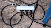
I solved the endless plugging-unplugging problem with a cheap multi-socket. No need to worry about current capacity when only one tool is ever being used. I can't be in two places at the same time no matter how hard I try. I have also learned to have a pencil in every place I am likely to need one. You would not believe how long it took me to get around to this. I even tuck pencils inside the ladder rungs to save me yet another journey down and back up again.

I had turned the dome around to face north while I worked on one panel. I glanced down while standing astride the stepladders with my head about 4' above the top of the dome. I was looking straight down through the open slit at the original ground level. It was the first time I actually sensed the full height.

I had used self-compacting sand and gravel to raise the ground level by about 1m or 3' below the actual building. Beyond that it falls away to the north. Even the floor of the observatory seems a long way below when I am standing on the top rungs of the stepladders.  The dome is 5' tall inside. The floor another 5' below that. Hopefully this means there will be plenty of room for a decent length of dewshield on my 7" f/12 refractor.

Tuesday: Another panel finished. A corner one again. Three easier ones to do. Warm and sunny. One more up. Two to go. And another. One more panel to go. Plus two small triangles next to the slit ribs.

Wednesday: Another warm and mostly sunny day reaching 71F. Last top tier panel finished by lunchtime. Only two small triangles left to do. Then I can start under bracing.

After lunch, rain stopped play. Artificial rain from a farmer's huge tractor and spraying machine with the wind coming our way.

With the last two small triangles fitted the covering panels are complete. I have run out of Sikaflex 591 sealer. So I ordered an extra couple of tubes online, in brown.


Click on any image for an enlargement.

*

2.9.18

Dome build: Top panels continued.

*

Saturday: Not a happy bunny. I have been playing with small scraps of 15mm ply. Trying to make the overlapping edge vanish by cutting back the underside. I wanted an overlap because of the low angle [22-23°] of the top tier of panels. It looks as if I'm going to have to cut back the undersides to rest on the highest cross struts. Then trim the overlaps back to the top edge of the lower tier of panels. Sealing the gaps will just have to do. Any upward projection looks awful. The low viewing angle greatly exaggerates the thickness of any overlap. Beveling the top edge, to make the leading edge thinner, is even worse!

Hours later I had shortened the three panels to stop at the next lower panels. I undercut the top panels to rest on the top cross struts for mutual support.

I also pulled the base of the ladder out. Then re-secured it so I could better reach the top of the dome.

Rotating the dome allows me to access the top from the inside stepladders. But my view is blocked once the top panels are fixed in place. I need to be able to see the top of the dome from very close quarters. To accurately measure and mark the panels for trimming.

There is now almost no extra height at the lower edges of the top tier. Which looks far better than before form below. Now I can press on with the rest of the panels in slightly thinner, 12mm, birch ply.

Sunday: Due to my temerity in cutting, it took me 2.5 hours to complete the first 12mm top panel to perfection.  The triangle was too large for either of my DIY, table saw sleds. Though I was able to cut across the bottom, the sides were far too long. So I cut roughly with an electric jigsaw and then trimmed back to the line with a No5 Stanley-Bailey plane. The shorter [side] panels will fit on my largest sled. Anything bigger would tip right off the small table of the DeWalt saw.

It is an odd situation trimming a trapezium or triangle. Cutting the top off lifts the whole panel. Cutting the bottom lowers it. Raising makes the base too wide. Lowering makes the base too narrow. It is a fine balance to achieve the correct dimensions and angles simultaneously. The tops are heavily skewed. The bottoms hardly at all. The 5th panel had to be notched around the right angle of the slit framework and mitered into the bargain. The next panels become straighter and much shorter. Hopefully making life very much easier.

I must have an altitude record for climbing ladders by now! Each panel is costing me at least ten climbs inside and ten climbs on the outside ladder. I'm sick of unplugging and plugging tools in. I was using the miter saw, table saw, jig saw and a router today.

Removing the riving/kerf knife from the DeWalt table saw, just to use the sled, or for half depth cuts is a complete bore too! The cover plate has to be removed and the blade wound up fully. Then a bolt head still deep within the machine has to be loosened enough to allow it to be pressed inwards. So that the knife can  be lifted free. After that the bolt can be re-tightened and the plate replaced. The blade can now be lowered and adjusted for the required depth of cut.  [If you can still remember why you went through all this rigmarole.

These two images show how little of the top tier is visible from the ground. [Upper image] The lower image shows the view from an upstairs window in the house. Eight panels were fitted at this stage.

Don't forget to isolate the saw first. Or your fingers may be sprayed across your face as you poke about deep inside the machine almost touching the razor sharp blade.

I'm prepared to bet that the idiot who designed this daft feature never used a circular saw productively in his entire life. Probably the same bloke, working well above his pay grade, who put the tiny OFF switch hidden away, down under the table. Where it can't be seen, nor reached, except with a white stick and the help of a specially trained guide dog!

Perhaps the overpaid "designer" idiot hoped that this would be a safety feature. Preventing the machine from being turned on by other than the operator themselves. Later machines [US only?] have a tiny red tab over the OFF switch to make it slightly easier to find in the darkness under there. But only for those with arms five feet [1.5m] long. My own answer to the problem of inaccessibility was covered in an earlier post:

 https://fullerscopes.blogspot.com/2018/06/dome-building-dewalt-stop-button-paddle.html

Click on any image for an enlargement.

*