31.1.22

31.01.2022 Consequences of cutting away a dome.

 *

Monday 31st. 36F overcast with brighter periods.

The positioning of the angle brackets, to hold the triangular, GRP patches in place, is quite critical. The large headed, galvanized bolts may match the rest, but their cosmetic appearance depends largely on symmetry. 

Of far more importance, the triangular patches also have some very real, structural duties. In the vulnerable areas on either sides of the slit. A hemisphere ought to be complete to enjoy maximum stiffness and strength from its geometric form. Making a large hole and then calling it an "observation slit" seriously weakens the structure.

Leaving large, triangular holes on either side of the slit is very bad form. The entire arc of the [foundation] base ring is missing unless supported by other means. 
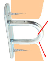
The multiple wheels/rollers, which support the dome and allow it to rotate, cannot support fresh air. The base ring alone has very limited stiffness over the open arc. The slit ribs help of course. Within their limitations. They are rather widely spaced and have little lateral stiffness without the help of the dome itself. Hence all the angle brackets double bolted along the edges. 

The upward pressure along that section of the base ring, which is not resisted by solid dome, could cause problems. It could bow upwards. Causing the dome to sag downwards. It could almost certainly throw  the considerable weight of the dome over far fewer rollers. 

I have "guesstimated" the dome's weight at around 500kg. The fourteen rollers would each support ~36kg each. If the entire slit arc provides no serious resistance then the load per roller might easily rise to 50kg. Or much more. Depending on the flatness of the rest of the base ring.  

Laminated plywood, glued in place and clamped is not a precision, flat surface. Though still, well within the load capacity of the rollers. The dome might become very difficult to turn. Or not turn as effortlessly as desired. I have repeatedly used the 360° laser level to check the ring for flatness. The large number of brackets holding it to the dome seem to help. My plywood dome relied only on the 8 ribs. With a little help from the cladding via some small screws. The base ring of that dome is more wavy than I'd like.

I speak from long experience in struggling to turn my 3m/10' plywood dome. It was very easy to rotate before the plywood cladding was added. Once clad, I needed a geared down, friction roller just to move the dome around.

Serious problems arose when the underside of the base ring has been wet from rain leakage. I then have to apply all my weight to turn the dome by pushing on the ribs in turn. The friction roller just spins uselessly. Regardless of my increasing its loading by hanging from the 2x4 lever. Hopefully[!] the GRP dome will be fully waterproof. So the base ring will not become soaked and slippery.

That said, the inside of the GRP dome is already sweating when the conditions allow. Which is why I left an annular space behind the base ring. To allow any condensation to run freely down to the skirt and fall off into fresh air. Failing that, I may have to glue [waterproof] coarse abrasive paper to the underside of the base ring. That will have to wait until the dome is lifted into place. 


*

30.1.22

30.01.2022 Triangular doorway patch.

 *

 Sunday 30th 41F, weak sunshine after the storm. No damage discovered so far. The wind is slowly dying down from about 29m/s gusts from the NW. Over 60mph. It might be worth trying to image later as the sun gathers its strength. The slit will be facing away from the wind.

 I spent the morning working on one of the triangular dome fillers. Lots of trimming helped to rotate the facets upright. To better match the shutters. Now I need to attach the triangle to the dome and slit ribs using brackets.

 When the weather is warmer I could fiberglass the curved edge of the triangle into the dome. The "gutter" over the original, arched doorway could then be trimmed back. Helping to improve the appearance. The gutter casts a heavy shadow. Which draws attention to it. As seen in the first image [Above, right] showing the exterior view.

 The second image shows the inside view. Ideally the triangle should be beveled on the curved, outside edge. Which would help to blend it into the dome's surface. The dome and triangle are both faceted. So matching the edges is not exactly easy. I must scribe the triangle to the slit rib. To close the gaps enough for silicone sealer to do its thing.

 I shall make a skirt for the bottom of the triangle to close off the 50mm/ 2" gap and make it wind and weatherproof. This will have to wait for the final arrangements of the bogie track. The shutter wraps itself around the triangle when closed. Adding to the complexity of working in 3D with all-spherical surfaces.

Imaging. After lunch. The seeing was awfully soft again. With a coarse grainy texture to the images on the monitor. No sign of any dew on the optics.  I tried Mono16 in SharpCap without the protective, internal filters. Still poor. Cloud has arrived. Giving up!

There is a new, ZWO camera driver which I had overlooked. V3.17. 9.6.2021. I have downloaded and installed it. Ready for the next imaging session.


 *


28.1.22

28.01.2022 Imaging in poor seeing conditions.

 *

Friday 28th 35F, clear skies! Early crescent moon low in the south. 

10.30 35F Optics dewed. Heat bands and hair drier making slow progress. 

11.38 [CET] 38F in the dome. Dew on objective  finally clear. Changed to 1.6x GPC to cope with the highly mobile seeing conditions. Rapid thermal shaking and soft focus. First [very poor] image. 

12.00 40F. Speckled, high cloud softening the image.


12.12 Still cloud around the sun.           


14.48 44F After lunch. No real improvement in seeing conditions. Sun now over the house. Cloud still present.

The image seems to be taking on a coarse, grainy appearance. Almost like my earlier ZWO ASI 120MC-S. That camera became unusable!


15.10 Changed to 2x GPC and removed the internal protection filters. Baader 35nm H-a and Beloptic KG3. With the sun so low and partially hidden by cloud its energy is much reduced. The Baader D-ERF can manage energy rejection on its own. A definite improvement.

15.25 The cloud is thicker than ever. 


There is  storm coming tomorrow. 29m/s or 65mph gusts are possible. I have turned the shutters into the wind to reduce any chance of lift. The telescopes are horizontal and under the polar axis. 


*

24.1.22

24/25.01.2022 Fiddling + spherical triangles.

 *

Monday 24th 41F, overcast again. No sun again!

I have been fiddling with the shutters and refitting brackets to the base ring. I doesn't sound much but it kept me busy for a few hours. I think I am going to have to use long, heavy duty, shelf brackets to fix the slit ribs to the base ring. There really isn't much room for anything else. Clearance is required for the hold downs on the inside track. The lower shutter bogies on the outside. 

Tuesday 5th. 41F. Overcast. I have been looking again at the open, spherical triangles on either side of the slit opening. Which will need to be filled with left-over GRP from the slit cut-out. The size of these triangles is very close to the total amount of reserve material available. With some further cosmetic limitations If I want to follow the dome's moulded facets.

I used brackets for the dome/base ring fixing. So I can now use more of these to hold the triangle fillers. Prior to deciding on using brackets I had imagined needing to use GRP or nothing else. A serious hurdle in winter. GRP is months away on minimum temperature requirements. Using GRP is quite possible later on. If I decide it is really necessary for sealing and/or increased strength.

I was also been fighting with the recalcitrant shutters. I cannot fill the triangles if I need them to access the dome.  I have kept the original doorway lip above. To ensure rain flows outside or over these triangles. It is time to see what can be done about filling in these triangles. Not an easy task using spherical off-cuts.

The results are shown in the images. Before, inside and outside.

It is very difficult to judge the curved, spherical edges. So I was very generous and still just made it within the available footprint. I have more than enough material left to form a skirt. The bottom of the triangle still needs to be trimmed to make it horizontal.

 I shall cut out the second triangle after lunch.

Preview of propped panel on 2nd triangle. The facets don't follow the dome. Nor the shutters. I have no choice given what is available. With careful marking I may be able to make the triangular panel more upright. I could use the remaining piece of GRP dome but it would mean a horizontal joint and even worse mismatch mid panel. Whether any of this can be seen from the ground is another matter. 


It rained in the afternoon. Making jigsawing on a mains extension lead a risk.


*

21.1.22

21.1.2022 Shutter improvement and ropework.

 *

Friday 21st 23-38F. -5+4C. Overcast.

 The shutters now work effortlessly with cords or fingers pulling or pushing near the top of the ribs. I can live with that.

 Here is a rough sketch of the rope layout for closing the shutters. Shutter closure pulleys are attached to the dome zenith board. They have to be spaced apart and the ropes crossed, just to be able to close the shutters fully and efficiently. The lower ends of the two ropes could form a closed loop to avoid duplication of effort.

 Meanwhile, the shutter opening ropes need a sunken pulley or eye bolt in each of the upper slit ribs. Otherwise the shutter ribs will strike the protrusion where they meet the slit ribs. Sash window style, fully enclosed pulleys are available from boating and yachting sources. 


 Or, a stainless steel padlock hasp could be fixed to the back of the slit rib. To protrude through a suitably beveled, rectangular hole. The rope should pass freely enough around the loop of the hasp to work effortlessly. Without any protrusion from the rib face. 

 Hasps could easily replace the pulleys on the zenith board and take up less room. Friction should remain low enough not to hinder shutter movement. It should be possible to carry the ropes down the slit rubs. Where the ropes can be most easily managed from the observatory floor. Perhaps with a little, manual help to keep the lower shutters in step.


 I still have to anchor the bottoms of the slit ribs to the base ring. They are currently resting on packing blocks. With a stud [long threaded rod] spanning the bottom of the observation slit to maintain accurate rib spacing. 

 Considerable trimming of the slit ribs was required to clear the lower, shutter bogies. One problem is leaving enough space for [storm] hold downs. To clear just above the base ring as the dome turns. Which makes bases of the slit ribs even more narrow. Precisely where they should join the base ring. A long, angle [shelf?] bracket may be necessary.

I may have to make filler panels for the cutouts from plywood. Then laminate more ply over the outside to reinforce these butt joints. Titebond III wood glue isn't rated for setting in winter cold. So this will have to wait.  

 As mentioned above, the shutter ribs close flat against the slit ribs in both shutter open and closed positions. So a large arc has to remain clear between them to avoid causing unwanted gaps. This sets severe limits on what is physically possible.

Perhaps I could/should re-fix the lower bogies to the shutter ribs with the shutters closed. Presently I am fixing the brackets with the shutters wide open for easier access to the brackets.  This is resulting in slight bowing of the meeting shutter ribs when closed. I might as well try and get it right. As previously mentioned [repeatedly] the shutters greatly exaggerate errors in the level of their support.


*

20.1.22

20.1.2022 Sticky shutter realignment.

 *

Thursday 20th 32F, gales from the NW. Early sunshine lost to clouds. 

I checked the alignment of the top bogies with my 4' level. There was about half an inch toe out in the middle. This couldn't be seen from the ground or inside the dome. I removed the fixing bolts and fitted another 12mm nut as a spacer only on the outer bolts. Once everything was tightened again the top bogies were now aligned.

 I bent the stay rods at the top to better align the channel. The rods were twisting the channel outwards. That helped too but there is still some sticking. I fitted a second wedge under the channel to maintain uprightness.

The bottom bogies were out of alignment too. I re-drilled the shutter rib for one bracket and that solved the problem. The shutters now run much more smoothly but still stick occasionally at the top. 

I must cure this infuriating problem before the dome is lifted into place. The observatory walls will add 1.5m or 5' to the height of the dome above the observatory floor. Making the top of the dome completely out of reach without a 4m+ ladder. I could fix pulleys to the zenith board to pull the shutters open and closed. I would prefer not to have to rely on such devices. 

The friction is caused by the aluminium channels rubbing together. Or the skate wheels dragging on the channel. Usually as result of the bottom of the shutters being out of phase with the tops. This shortens the shutters and twists them diagonally. 

I tried greasing the channel overlaps without obvious improvement. Perhaps plastic, file binder, slipped over the edges of one channel, would help? Plastic against aluminium can't be as bad as aluminium dragging against aluminium. I was still adjusting the lower bogies when it became too dark to continue. The sun never did show itself for long enough to make imaging worth the effort.


*

19.1.22

19.01.2022 Sticky shutters.

 *

Wednesday 19th 38F very heavy overcast. Wet and windy.

I only needed a lower curve on the [studs] threaded rods I used to reinforce the top channel stays. The rods then passed vertically through the 10mm holes in the outer ends of the channel.

I did not mention that I added a plastic wedge between the top of the dome and the channel. The curvature of the dome had leaned the channel away from the zenith board. Which made the skate wheel hubs drag on the top edge of the channel. So I brought the channel more upright to combat this problem. I have lots of these carpenter's wedges. Which I had used to match the shelf brackets to the base ring. So I can increase the tilt if it proves necessary. They are very robust under compression.

The lower channel has yet to be fixed to the base ring. I am trying to achieve an accurate idea of the required spacing and degree of parallelism with the upper channel. More on this later after testing the shutter movement. 

The shutters proved to be variable. Sometimes they would open effortlessly. At others the tops would stick. I removed the bottom channel. Then clamped spacers to fix the plank on which the skate wheels now ran. This was a definite improvement. I have been deliberately using overlapping channels of different sizes. Which meant aluminium rubbing against aluminium with the slightest misalignment.

There is a high point on the shutter ribs. At which pushing and pulling produces the smoothest movement at both top and bottom. I'm going to think about this problem before trying to fix anything. The shutters are usable, but a nuisance, as they are. There is no obvious way to stiffen them diagonally. Because the inside of their [spherical] curves is swept by the slit ribs.  


*

18.1.22

18.01.2021 Studs for stiffer stays.

 *

Tuesday 18th 40F.

 My need for a stiffer stay for the top channel has been answered. I shall use an M10 galvanized stud [threaded rod or all thread.] This is the same size of the galvanized bolts holding the dome segments together. If the 10mm proves inadequate I can increase the diameter to M12.

The bottom of the stud can be bent to pass through the dome joint perpendicularly. Similarly at the top, if needed, to pass though a hole in the channel. Galvanized nuts will clamp where necessary. With a large, stainless steel washer and rubber tap washer sealing the dome as usual. 

The bare, threaded section, in the middle, can be sleeved with an aluminium tube for neatness. With luck it may even provide some extra resistance to compression loads and bending. 

The top fixing, in the channel, is well beyond the outer travel point of the skate wheels. Should the shutter overshoot [highly unlikely] it can be safely stopped here. The advantage of studs is easy adjustability for channel level. Whether the perforated strip stays will still be required I shall only discover when the studs are in place.

The image at the top of the page shows the first threaded stay. Putting a bend on the end of the rod required considerable effort. These threaded rods are stiff!  The result of adding a compression stay was a very rigid assembly. I tensioned the perforated stays until they rang on being tapped.

Now for the stays on other end of the channel. Done in a flash! The channel feels rock solid. I shall leave it until tomorrow, and daylight, to test the shutter movement. The lower channel has yet to be fixed to the base ring.

*

17.1.22

17.01.2022 Upper channel stays.

 *

Monday 17th, 38F, gales and some sunshine. The NW wind is on the back of the dome if I wanted to do some imaging.

Today's priority is building some stays for the top guide rail channel. I went off the idea of using some existing box section aluminium. The wall thickness really wasn't adequate to the task. Not when using my tabs idea.

 I had planned to cut away a rectangular section of tube to leave just one wall as a fixing tab. However,  the considerable weight of each shutter deserves far more reliable support. Aluminium readily work hardens with flexure. A recipe for disaster!

I have mentioned not liking steel due to corrosion issues. However, I have a roll of perforated roofing strip. This is galvanized to avoid rust. The strip is usually found hidden away in roof constructions. Commonly used for triangulating against wind loading. The strip is much slimmer and far easier to install than fixing diagonal, timber braces. Which can only work in compression. [Rather than tension.]

What I do not like is the cosmetic appearance. It is neat enough, in itself, but just doesn't look the part being so exposed on top of my observatory dome. Then I had the idea of sleeving the steel strip with the original aluminium box section tube. Strength with smartness? We shall see.

The perforated steel strip was not remotely stiff enough to do anything useful. Even though it felt stiff in the hands. It simply bowed under compression. The angles required for fixings were also quite complex. Meaning that a much stiffer strip would need compound angles to lie flat on the dome. The perforated strip was thus a useful tool. To help me judge the requirements, angles and dimensions.

15.00 38F Tried imaging. Sun just above the roof. Mush! 15.27 Different area. Mush! 15.30 Lost  below the house roof.  

Later I applied inverted imagination. The top channel stays can be in tension. I just need to fix supporting blocks, for the channel, as far outboard as possible. Or, I can add a vertical strut from the central bolt up to the channel. 

*

16.1.22

16.01.2022 Yo heave ho!

 *

Sunday 16th. 37F. It is 8.00 and still far too dark to see anything outside.

The task today is to bodily lift the remaining shutter. It slipped as I removed the last screw holding the upper drawer slide.  The bottom of the shutter is resting on the ground. With the upper end inside the zenith board. I propped it with lengths of timber to ensure it didn't fall right off during the night. 

It was already pitch black by the time I had finished the struggle with drawer side removal. There was no direct line to use the power drill screwdriver even with driver extensions. Nor even a Torx screwdriver. I was using my largest, straight bladed screwdriver to lever the last screw out. I had to hammer the screwdriver in behind the drawer slide. Fortunately there was no damage to the shutter woodwork. Even the drawer slide seems to have escaped unscathed. 

The lift requires I hook the top board over the zenith board. Meanwhile the bottom bogie will hook itself under the base ring. The shutter is far too heavy and too far out of reach to do a straight, manual lift from inside the dome. 

I am thinking of using long lengths of 2x4, resting on the ground inside the dome, as ramps for the top end. They will project just far enough to allow the top board to rise over the zenith board. While I shall be lifting outwards and upwards at the base using levers. 

Well, it's a plan. Not a great plan. I am still trying to insert the boat winch somewhere into the equation.  I have an hour or two to come up with a better idea. Showers are forecast with gales later.

Just had a look in daylight. Drizzling steadily. I need a long diagonal board from outside the dome. To slip under the shutter top board and over the zenith board. Then I can control the lift from the bottom. It sounds far too easy! 😎

The diagonal 2x4 ensured the shutter did not drop inside the zenith board during the big lift. Once I had the bottom of the shutter off the ground I could get my hands underneath. There followed a huge, manual lift. The shutter was safely hooked at the top but still badly skewed. After much heaving and levering the shutter rib was lifted outside the slit rib. The skate wheels then dropped down into the channel. Which, incidentally, is still unsecured. See image above for proof of my success.  

Now I want to push the bottom channel under the skate wheels. This will [should] provide the vital stability to the shutters. Until the top channel rail is properly stabilized with stays.

15.00 42F. It brightened up. W-NW Gales forecast for all of tonight and early tomorrow.

It soon became overcast again with drizzle. So I cut short my time outside as the light quickly failed. I have shortened the bottom channel and run it under the skate wheels. There is a difference of about 15mm in the distance from the channel to the 4' level. Which I have hanging from cords from the zenith board as a reference. This difference can be adjusted out by changing the height of the relevant bottom bogie bracket[s.] Lowering them on the ribs will push the channel further out.

I finally have the inner, shutter ribs parallel and close together. Which is a first. They have always been out of level with each other when supported by the drawer slides. No to mention bowed away from each other. They were easily clamped together just now. For security during tonight's potential stormy weather.


*


15.1.22

15.01.2022 Top bogies continued:

*

10.30 34F outside, 36F inside. The sun has finally reached the dome. Imaging? I'd better give it a try. Or not. It quickly clouded over from the west. So much for the sunny forecast. The optics are dewed over but responded to the hair drier. No real point in continuing with all this cloud masking the sun.

I did find some rectangular aluminium box tubing for the rail struts. I'll cut back enough of the section to leave a tab on each end. Which can be drilled and bent to provide the fixing point. The struts will be roughly 35cm long. If I clamp the channel to the zenith board there will be no need for end resistance. I do not want to drill the channel anywhere near the center. To avoid weakening it. Nor drill down through the top of the dome in case of leakage. Any rainwater drips would be right over the equipment below.

The second, top bogie is now fitted to the other shutter. Removing the drawer slide was an hour long nightmare! Getting at the screws on the inside of the top board was very difficult even with a torch and mirror. The incredible retaining power of such tiny Torx screws was unbelievable. 4.5x20mm. 

Thanks goodness the lower drawer slide broke while the dome was still on the ground! Giving me a vital warning of their vulnerability. It has been a marathon to replace them with skate wheels but it is well worth it. The shutters are too flexible to allow the much greater precision demanded of drawer slides.

Hopefully the twin, channel tracks will solve this issue. There is enough freedom for the wheels to take their own path within the channels. Without worrying about diagonal tension. The skate wheels roll effortlessly compared with the drawer slides. Which should mean that the shutters should move as one. Rather than the top or bottom lagging behind. 


*


15.01.2022 Top rail-channel struts.

 *

Saturday 15th 29F. Another cool but sunny day is promised.

 I need stabilizers for the top guide rail/channel. Though I haven't really thought about the problem until now. The drawer slides were doing all the work. Until I took one off and discovered that shutter was no longer stable.

The image gives a very rough idea of what is needed. I have drawn in struts to show the general proportions. [Not remotely to scale!]  The top rail-channel is too short. The struts would be upright as seen from this angle.

BTW: The gently sloping ladder has a large and heavy paving slab lying at the base to stop it sliding away. The pipe insulation quickly proved to have enough friction to fully stabilize the ladder. The pipe insulation also protects the dome against cosmetic damage. 

I always adjust the ladder and paving slab to avoid all rocking before adding the pipe insulation. This arrangement has proved very safe in use. Without a single worrying moment. Access to the top of the dome through the top of the slit is via a sturdy [Japanese] tripod stepladder. Though this obviously requires the shutters are open. Which is not always the case.

 The guide rail-channel has to remain level under widely varying and dynamic loads.  Resistance against twisting and longitudinal movement is vital. Which means triangulation is required. The support struts need to lean inwards from the dome's segment joint. Which is outboard and below. Where there are plenty of existing M12 bolts to choose from as secure fixings. I do not want to make fresh holes in the dome if I can help it. Even though I use rubber tap washers to weather proof each bolt.

Strips of aluminium would need to be thick enough to resist bending. Making the end bends then becomes a problem. Heat treatment? A flat, triangular plate with tabs might work. Tubing must be flattened at the ends and then bent. Though the 12mm bolts place minimum dimensions on the flat sections. 

I automatically think in terms of aluminium because it is easily worked. Not to mention corrosion free without further treatment. I am not a fan of rusting steel and try to avoid it. 

Which leaves stainless steel. A stiff, hard material. Which is difficult to drill and saw with used tools. It easily work hardens if the active cutting edge becomes dull and starts rubbing. I would need ready-made strips of suitable dimensions. Sawing from flat sheet is a complete non-starter.

 Is there anything "off the shelf" which might become useful struts with only a little imagination? I had better do some measuring first. The dome was covered in rime frost "fur."


*

14.1.22

14.01.2022 Lunar imaging


 *

Friday evening: 

18.30 36F outside, 41F in the dome. Moon high in the west. First image. Not very sharp when enlarged. Some low frequency thermal agitation.


18.42 Refocused. D-ERF still in place. More processing than the last to reduce contrast.


 18.50 Plato is showing a central craterlet.


18.57 Changed to 2.6x GPC  Plato showing four craterlets. Three single and one double.


19.00 Tried the 2x Shorty Barlow. Far too soft! Removed the D-ERF. Even worse!


19.17 Back to the 2.6x GPC + D-ERF.


 19.25 Tried 16 bit.


19.37 8 bit.


19.40 Dinner.


20.39  39F inside the dome. Back after dinner. Moon high. Slight halo. Slightly more stable image. Salopettes and second down jacket.


20.50


 20.56

 21.05


 21.15 Giving up. The seeing is going soft despite the high lunar altitude. 57.5°. I can no longer see the Plato craterlets on the monitor.


*

14.01.2022 Top, shutter bogie progress then whoops!

 *

Friday 43F, overcast start with drizzle. Later I managed to get some M10x60mm bolts. So I can fit the upper bogies this afternoon. Though it has become sunny now and I should be solar imaging.

The seeing was horrendous! Violent thermal agitation and mushy detail. This was before the sun was over the house. So I couldn't blame the roof.

After lunch I drilled the bogie channels for the socket head bolts. 10mm right through and then 16mm for head clearance. I shall have to look out for 16mm rubber stoppers to keep the rain out.

The shutter top boards are birch plywood laminated to 40mm thick. The channels are 5mm thick. The 60mm bolts may be slightly too long. The protruding axle nuts will require sink holes. Or matching packing on the fixing bolts. I will order stainless steel bolts as appropriate. 

That can wait until after a trial fitting. I don't think the drawer slides will get in the way. Which is why I placed the bolts so high up. To ensure clearance. The positioning of the bolts was very limited by the skate wheels. 

There was also the matter of overlapping channels. I wanted to match the bogie rolling height to match the drawer slides. I can still remove the drawer slides after the bogies are in place.  Not before. Or the shutters will be unsupported.

I managed to fit one bogie using 12mm galvanized nuts as spacers. However, the shutter would not move because of obstructions to the drawer slide. I removed the drawer slide, in the dark, by torchlight. The shutter promptly fell sideways as the rail channel tipped upwards at the far end! Fortunately the shutter remained hooked in place on the ladder. Which I had been using to extract the last of the screws.

A ratchet strap, hooked under the dome skirt, pulled the channel back down to level. Then I could close the shutters for the night. It should be sunny and dry again tomorrow. So I can continue work. First priority is making sturdy props for the top, rail channel!


*

13.1.22

13.01.2022 Shutter progress.

 *

Thursday 13th 43F, milder but overcast and breezy. 

The flanged M10 stainless steel fixings have just arrived. Excellent service from the climbing shop! The flanges are slim enough not to obstruct the shutter movement. A 12mm hole is bored in the plywood to accept the taper. The nut is inserted from the far side of the board to achieve automatic locking by friction. Though the three holes can accept screws. To ensure the nut does not rotate if corrosion occurs over time.

I have used T-nuts for years. So I am looking forwards to having a new form of fixing. These are not unlike the furniture nuts I used on my big GEM mounting. Being stainless steel and much larger, makes these new nuts much tougher. Having new materials is apt to introduce fresh ideas in other areas.

The problem now is that I have no M10 bolts to clamp the bogies to the top boards. This has to be done with some care. Otherwise the channels will be squashed inwards and overload the wheel bearings. It will require internal spacers over the bolts to resist the bolt's compression. [Fiddly!] 

Or, shorter bolts passing through the far side of the channel only.  Probably requiring hex socket head bolts to allow them to be driven through a smaller hole in the outer channel flange. It would be impossible to reach hex head bolts once the bogies are in place. It would require very large holes for a socket to reach a hex head. Which would weaken the defenses against the weather.

What are the chances of finding M10 hex socket head screws or bolts, in stainless steel, on the shelf of a local DIY store? Probably nil. Which means I will have to order online. It's Thursday. So I shan't see them until Monday. Three days lost. Perhaps I should order the stainless steel. Then go and collect zinc flashed, socket head screws to be going on with.

The image [above right] shows how many clamps are needed. Just to add a single reinforcing bracket. To tie the top board to the inner shutter rib. It took me ages to find a suitably sturdy bracket due to the extreme overhang. I had to notch the rib to allow the bracket to fit under the shutter cover. I am using M10 galvanized bolts through the bracket and shutter cover. I managed to complete fitting the second bracket before it was fully dark. With the help of a torch to drive the Torx screws. It was so heavily overcast all day that it didn't really achieve normal levels of daylight.


*

12.1.22

12.01.2022

 *

 Wednesday 12th overcast and misty. 

 I have been mulling over the fixing of the bogies to the top shutter boards. The idea of using the axles as fixing points makes much less sense now I have had time to think it over. It would involve detaching wheels, bolts, nuts and spacers. All in a very inaccessible situation high above the ground. 

 Far better to have the bogies detachable as complete units. To be worked on in comfort on the bench. Where the components can be dismantled if needed. Without loss of vital parts requiring further construction.

 The bogies would need to be lifted upwards to clear the channel for maintenance. So I need bolt fixings from fixed nuts. T-nuts are only available in coated steel. Which would be corroding before they even left their costly bubble pack. 

 I need some other form of furniture assembly nuts. Preferably in brass, aluminium or stainless steel. Time to do some more online homework.

 That was easy: I found these sturdy, stainless steel, M10 fixings. Used for holds on outdoor, artificial climbing walls. Cheap too, compared with online, fixing specialists at 10x the price! Duly ordered. I'll fit them from the inside of the boards. Then the fixing bolts will be trying to pull them right through the 24mm thick, plywood boards. Which would provide as much retention as desired.

 I spent the morning swapping the plain nuts over to Nyloc locking nuts. I find it is always best to wait until fully satisfied with an assembly before using locking nuts. Otherwise it wears out the locking mechanism. It also causes endless delays if something has to be repeatedly dismantled and re-assembled using tools. Instead of finger tight, plain nuts.

 The lower bogies are proving difficult to align and simultaneously achieve the correct shutter height. The lower ribs drag on the dome when there isn't enough clearance. The lack of concentricity is obvious to the eye from the outside. Though not remotely obvious when working on my hands and knees on the lower inside of the shutters. 

The shutters swing outwards from the pivot point at the top drawer slides. Gaining more height involves pushing the shutters outwards and lowering the bogies on the ribs. Each end requires a different height to make the 3D spherical shutters concentric in all planes.


*

11.01.2022 [2] Bogie spacer progress.

 *

The skate wheels have just arrived in the post. It is grey and slightly misty but not too unpleasant to be out of doors. I have run out of suitable spacers to keep the wheels central in the bogie channels. I had been using 10mm nuts as spacers but they are too large for the wheel bearings. The spacers only want to contact the inner race. Otherwise they may short circuit the freedom offered by the wheel bearings.

I found some Pex-pipe in my collection. This hose slipped just nicely over the 8mm axle bolts. Pex is a tough, hard and stiff, plastic pipe. Much used for plumbing. 

The problem is that I don't have any proper cutters for this material. It needs a clean, square cut for the spacers to be useful. Sawing just produces a rough, furry cut. As does sanding. 

I need 32 spacers of the correct length. To take up the slack and gently end load the bearings to avoid tilting. So now I have to go to the builder's merchants to buy a pair of Pex pipe/hose/tube cutters/snips/scissors/pliers. Correct name according to geography. 

The cheapest are about £12 [equivalent] each but invaluable for repetitive, clean and square cuts. They come in all sorts of designs and prices. Even electrical and rechargeable versions. Which I don't need for the very limited use I shall give them. 

32 spacers later and the skate wheel bogies are all but complete. The budget Pex cutters worked very well. Though I imagine the effort required would rise considerably with larger Pex hose diameters. The cost of the pliers is offset by the toughness, long life and lack of corrosion of Pex pipe. 

I considered making brass wheel spacers but there is an unfortunate combination of different metals. Probably leading to ugly staining. Then there is the time involved in producing them on the lathe at zero degree C in the workshop. Besides, there is very little lateral force on the wheel bearings. So the Pex spacers should last well.


*

11.1.22

11.01.2022 Shutter bogies and a raised, working platform?

 *

Tuesday 11th 36F, overcast.

The second set of 84mm skate wheels should arrive in the post this morning. 

I plan to fix the 48cm long, top bogies to the shutter boards via the wheel axles. These will be long, stainless steel bolts with stainless Nyloc nuts. Here, I have mocked-up the fixings with temporary studding to test shutter movement. The dome was completely covered in black ice! 

I should be considering adding several eye bolts to the dome segment clamping. This will provide secure tie-off anchors for ladders when the dome is raised. Though a horizontal rail would be more secure. Giving the ladder something to rest against. This would need sturdy stanchions.The dome can be rotated to bring it to a suitable position for better working access from the front of the building. 

Though a working platform, stretched between the buildings, would be better still. Allowing much safer access to the outside of the dome from skirt level. I'll have to give this idea some serious thought. Access to the dome's exterior will inevitably become ever more difficult with my increasing age. [75 and still rising] 

Avoiding towering ladders, resting on the curved dome from ground level, would be very sensible indeed. I could fit some of the old veranda, meshed fencing to the back of the platform for safety. The ridge of the adjoining shed is close to level with the top of the observatory building. 

Why haven't I thought of this before? It would solve a number of access problems. The platform could even be accessed though the open slit from the observatory floor. Using a secured stepladder after the dome was turned to face east. No ladder access required from the ground. Then the platform could be securely fenced, front and back, to avoid all risk of falls.


Bolting the bogies to the top boards will ensure firm, long term support. The sides of the bogies will lie flat on the boards. So should be simple to work on in the event of any future problems. The shutter, top boards are accessible on the inside when the shutters are wide open. Provided I can reach them!

It might be sensible to bolt through between the wheels. Then the wheels could be changed individually. Without losing the bogie's support for the shutters. I'll ponder on that before making a decision. Meanwhile, I'll be using the four M8 axle bolts per bogie anyway.

The drawer slides are a nightmare to work on when in place. Multiple, small, wood screws are progressively covered by the slides. With access to the screws only via small holes when the slides are in fixed, relative positions.  The screw heads had to be a particular size, 4.5mm. To fit the fixing holes without obstructing the slide movement. 

The skate wheels are already proving their value in low friction and rolling resistance. Months of struggling to open and close the shutters is finally coming to an end. I have often had to use a long batten to just get the tops of the shutters to move. The drawer slides were just not up to the loads being applied.


*

10.1.22

10.01.2022 Two top bogies and lunar imaging.

 *


 Monday 10th 35F overcast. The new skate wheels won't be here until tomorrow at the earliest. If it remains dry I can saw out two more bogie channels from the 2"x6" aluminium box section.

I have looked at the position of the axles, on the existing bogie channels. There isn't much room for asymmetry in the channel sides. It would also make smoothing the saw cuts far more difficult than it needs to be. 

The bogies could be made from flat plate and a much smaller box section simply bolted together. It was sheer luck I have scrap box section available. It will provide better shelter for the wheels. Whereas built-up channel sections might leak rain through the joints. Unless silicone sealer were used.

Two upper bogie, channel housings are sawn out and the edges smoothed. They just need to be drilled for the 8mm skate wheel axles. Still awaiting confirmation of dispatch of a new set of 84mm skate wheels. The shutter, with two skate wheel bogies, ran very smoothly and freely. The top drawer slide must have been slightly unloaded by the top bogie.

Late afternoon the moon was rising in the SW. I captured a load of images with the 2x GPC and the D-ERF still in place. ICE mosaic 3659x2382 pixels 8.72MP!


18.38 36F Freezing ! More processing in ImPPG. Seeing is slightly better than an hour ago.

Had to go back indoors for a second down jacket and salopettes.

18.48 Trying the 2.6x GPC for more scale. Slight halo around the moon now. Thin high cloud?


 18.55  32F Different area. The seeing has become thermally agitated.


19.30 Gave up trying to sharpen softer images than earlier.


~~