28.12.21

28.12.2021 Pause for thought.

 *

Tuesday 28th 32F, cold, dark, overcast and quite windy. Snow still lying thanks to continuous hard frosts. 

 Images of potential details are rehearsed in my head. Though no real progress on the new observatory. Nor on the dome. My creative thoughts continue on tick-over. It is too unpleasant to do any outside work. There are no gloves which insulate against horribly cold metal. While still providing the necessary dexterity to handle small fasteners. There is no hope of finding anything dropped into the snow. 


*


26.12.21

26.12.2021 Imaging.

 *

Sunday 26th 18F air temperature. Snow lying. Hard frost.

09.25 [CET] Set up for solar imaging. Dome at 21F inside. The rubber skirt was frozen to the base ring timber. Making dome rotation impossible until manually freed all around. The  dew bands have risen from 18F to 54F so far. No sunrise yet. Cloth cladding inside of the dome frosted over. I am using fleece gloves with fingertips cut off. Still bitterly cold on my fingers when typing!

09.35 Sun has risen but is completely blocked by the absent neighbour's 8m/25' hedge! This is going to take some time to get a clear view!

10.00 Back indoors to put on my salopettes and warm up. The shadow of the hedge is still solid on the lower half of the dome. Sunlight grazing across the top of the dome. Patchy ground mist is rising. With the the present sun's path I may not have a clear sun until it reaches the south.

10.29 First image despite dewed optics. D-ERF, objective, etalon and 1.25x GPC all dewed.  Dismantled and used the hairdrier. Tree now blocking the view! Dew band reached 72F.


12.29 I have spent the whole morning trying to achieve sharp focus with visible H-a detail. Tried re-tuning the etalon dozens of times. No improvement. Tried checking the focal point and adjusting the position of the etalon. Tried lots of capture frame sizes. 

Changed the settings repeatedly in AS!3. I removed the etalon and filters and examined the image of a distant tree with an eyepiece. It seemed okay.

Finally, I tried the Lacerta 2" wedge for white light. 2.6x GPC. Left the D-ERF in place. Image heavily cropped.


*

26.12.2021 Solar imaging strategy.

 *

Sunday 26th 19F, -7C at 08.00 CET. Another cold, sunny day is forecast. A bright, half moon is high in the SSW. There is a large group, of large sunspots, in the south east solar quadrant. [AR2916] A second, less dramatic group lies in the north east quadrant. [AR2918] So I really ought to make an effort today. 

The optics are almost certain to dew over when uncovered after another hard frost. The dome warms when the shutters are opened and the interior exposed to the sun's warmth. Meaning that the optics lag behind the rising air temperature leading to condensation. The dew bands will need to be switched on early. Even before the low sun clears all the local obstacles. No doubt I shall need the encouragement of the hair drier. I shall also have to wrap up warm myself!

I have been advised to reduce the number of stacked images I habitually use. Presently 75 out of 500 captured in SharpCap and processed in Autostakkert AS!3. As the advice came from a highly skilled solar imager I really should experiment. His images are often so much better than mine that there is simply no comparison.

Regarding image size I have tended to use the most powerful GPC I can get away with. Depending on the seeing conditions on the day. There is a clear tradeoff between increasing power and a smaller field of view. 

Where detail is spread over several fields I could build a mosaic. Rather than using a weaker GPC in the hope of sharper detail and a wider field. Wider fields risk finding the PST etalon's sweet spot. This is a geometric limitation. Where a larger aperture, longer focus lens is used with too small a diameter of etalon. Resulting in a limited spot or ring of better H-alpha detail but with bland areas all around. 

Larger aperture etalons cost a lot of money! Hence the number of solar imagers. Who "borrow" the PST etalon from inside a Meade 40mm H-alpha telescope. Then fit the etalon to the H-a filter stack behind larger instruments. In what is known as PST Mod. [Modification] Provided the larger telescope works at f/10, or can be made to do so, the results can be astounding. Though [sadly] etalons vary widely in quality and bandwidth.

There are alternatives but none can be called "budget." Even these devices are open to wide variations in quality despite the very high price tags. Some of these options also have optical or thermal limitations. With long lags for internal heaters to work as intended. Or needing built in Barlows to work at f/30! 

Despite the increasing popularity of H-a solar imaging, it is still a narrow interest hobby. Making economies of scale, with volume production, a bit of a non-starter. Only a very few companies are involved in etalon manufacture globally. So market competition is relatively weak. A larger etalon can cost as much as a small car.

 All of this information is available online using suitable search terms. Or discussed on generalized, astronomy forums. The largest and most active, specialist, solar forum being SolarChat! Where some of the finest solar images, produced by skilled amateurs, can be seen on almost a daily basis. 

There are sub-forums for discussion of instruments, modifications, processing and techniques. The regulars are a friendly bunch and bent on the improvement of instruments and techniques. Rather than cut-throat competition for attention or who can spend the most. Some skill and experience is required before even the most costly equipment will perform. 

Every imager and observer is limited by the seeing conditions on the day. Those who live nearest the equator are not guaranteed improved seeing conditions. Their reduced path length of atmosphere, with the sun usually high overhead, may suffer thermally unstable air. While those languishing in the far north. Can enjoy moments of fine seeing provided the sun is actually above the horizon, or above local obstacles. 

Imagers and observers carry out their work/hobby in widely varying conditions. From balconies on high rise buildings. Or from their gardens in cities completely surrounded in city buildings. A little direct experience will tell. Whether a certain location enjoys suitable seeing condition. Often enough, to make the investment in time and equipment worthwhile. There seem to be no hard and fast rules.


*

24.12.21

24.12.2021 "Bent" Astrograph Pier and imaging desk.

*

 My posts keep getting longer and longer as I think of new ideas. So I have had to split up the last post on the new pier. There's humour [pun] in there somewhere.

I am now leaning [another pun!] towards a more compact, more vertical, offset pier up to the Obs. floor level. The 55° bend will be reinforced with multiple layers of vertical 18mm plywood. Both externally and internally. 

The leaning section at 55° will have a square cross section of about 40x40cm. With solid, 4x4" timbers in the corners for stiffness. All clad in 18mm plywood. The leaning section will be about 250cm along the top. Measured up the incline from floor level close to the south wall. I leaned a pole against the mounting to find a suitable position for the axes crossing point. Even this simple action was balked by the presence of the original observatory walls.The new building walls are at least 30cm beyond the present north and south walls.

Ideally it should be possible to walk around, or step over, the base of the pier where is rises from the floor. This will avoid having to move about under the bulky, mounted instruments. I shall have to move the RA wormwheel to just under the Dec housing.

______________________

I still haven't a clue where my imaging desk will go. The instruments will pass right through the area under the north pole. Which is where my desk is wrapped around the present pyramidal pier. I may end up facing the SE or SW observatory wall. This would provide better shelter from direct sunshine and wind. Though my own body heat might rise through the telescope's light path. 

I hardly dare mention the need for my 27" imaging monitor. Will it need to be moved around too? Two fixed cables. The screen best facing north to avoid direct sunlight and/or a bright southern sky. It presently sits on a universal mounting plate on the north face of the pier. A definite No-Go area with the astrograph mounting.

It isn't a simple matter of fitting wheels or castors to a mobile desk. There are multiple cables to manage. Wireless control of the drives is not a feature of AWR[Tech]UK. Only my mouse and keyboard are wireless. 

Still without computer control thanks to continuing problems with the ASCOM[AWR] driver. So I can't manage planetarium Gotos or even return to Park. Not that it ever went directly to anything [at all] in all the time I have been paying £50 a year for it. 

The observatory will be over  a meter greater in diameter than at present. Which suggests much more room is available. However, I shall be housing longer instruments. Which wouldn't swing inside the present 10' dome. So I have been concentrating on high resolution, [closeup] Solar H-alpha with the 6" f/10 refractor. Albeit with a long filter stack projecting from the focuser. 

Both the 7" f/12 and 10" f/8 demand a larger turning circle. Moreover, they will swing in areas presently denied to them by the German Equatorial Mounting's severe, geometrical constraints. One can't mount large instruments on either end of the Declination axis. Not without endless collisions with the pier. If one instrument is looking east or west above the Pole. Then the other must [inevitably] be under the pole and facing exactly the same way. When they are pointing south then they will fill an area above and below the pole. Taking up much of the northern floor area and southern dome space.

A fork mounting might do it. Provided one were willing to limit pointing. To the area of the sky well away from the Pole. A fork, long enough to allow such long instrument to pass safely inside it, would be prodigious! The ridiculously long fork tines would be trying to bend in all directions. 

Better to let the pier take the strain. A pier can be built as massively as desired or needed. With the Dec axis a simple bearing box. Rotating on a Polar Axis plate. Which is sitting right on top of the sturdy pier. 


 *


24.12.2021 White Christmas Eve

 *

Yesterday's 1-2" of snow lay about over everything this morning. 


 A fresh snow scene of the observatory building site. Christmas Eve 2021. It is difficult to judge the scale of the new dome when it is in the foreground. The old plywood dome is both further away and much higher. 4m from the ground to the skirt.

 Careful study of the image will show a thin, green arc drawn over the image of the plywood dome. Representing the 4.3m dome compared to the old 3m. [14' : 10' in Ø]

 Click any image for an enlargement.


 Here I have [roughly] painted in the larger green dome for a better sense of scale. I think you will agree that it shrinks with distance and height. The green digital "paint" is a bit bright and dead flat compared to the fiberglass. I have made no attempt to soften it with shadows and highlights.


  The shiny, green, fiberglass dome readily reflects its surroundings and the sky. Note the countless variations in tone due to the horizontal facets. These will further soften the dome seen from the ground or at any distance. The shutters have the same [3D] facets and colour. Albeit at 90 degrees to the dome. Which will still [hopefully] further break up the hemispherical outline.


*

22.12.21

22nd "Bent" Astrograph pier continued.

 *

Wednesday 22nd 36F, misty with a heavy overcast. 

Continuing on with different ideas for the bent pier: The upper, leaning section could be pivoted in the vertical direction. A massive weight would counter the cantilevered load on the far end of the sloping PA housing. 100kg load x [say] 1m overhang needs a couple of hundred kilos at shorter radius to balance. 

I only suggest this idea to allow the PA to be more easily aligned on the Pole. The footprint of the lower pier could be shrunk slightly. Much depends on having room for the stepladder to the observatory on the first floor. My rough drawings, in the last post, have long, leaning timbers passing through the present ladder position. 

Even with a bend at upper floor level the pier still needs to be about 14' [4m] high. It demands adequate support against applied loads with considerable moment. Hence the massive timber pyramid stretched to fill the entire space in the observatory. 

With four 4x4" timber legs, this pyramid pier has been as solid as a rock. Despite all the weight mounted on its top. I have made numerous checks with lasers. As I applied heavy rotational force at the mounting platform with a long bar. The pyramid seems very stiff in all directions. Far stiffer than many tripods could every claim to be. It hasn't sunk according to my measurements. 

The four supporting, foundation blocks rest on well compacted, self-stabilizing gravel. Each with a footprint of about 1 square foot. Four square feet would not be considered a very large concrete block if the pier were a simple column 14' [over 4m] high. However, there are none of the normal toppling force applied to the widely separated footings. 

A "bent" pier will not change the forces applied to the footings. Except by a small amount due to new timber and plywood cladding layouts. The center of mass still lies at the center of the dome. It is concentrated in the heavy mounting and the instruments. 

The offset, due to the bend, will apply new and different forces as the telescopes are moved around the sky. Wind blowing on the instruments will apply more torque to the offset leaning section than at present. External forces must be resisted with large cross sections and stiff constructions. 

Thick plywood has excellent resistance in its own plane provided it is well fixed to the timber beams. Though plywood will happily "breathe" slightly between supporting timbers. Which can introduce resonance. 

Internal plates, or shelves, can provide massive resistance to bending of plywood cladding. They make far stiffer box sections than applying battens between timber supports. Or even doubling the plywood thickness. I have decades of experience in building loudspeakers and very large subwoofers. Though far more compact than my giant pier, they suffer from exactly the same problems of [potential] flexure.

Perhaps it is fortunate that I do not own a welder. Otherwise I'd be trying to build a massive contraption out of pipe. Which would be far more likely to vibrate when subjected to external forces. The major problem with timber is the sheer bulk. Which has to penetrate the floor between the existing joists. The various rough drawings don't show that the legs [below floor level] are widely splayed. Though remaining confined within the enlarged, floor plan. The clear space outside the old observatory remains hidden by the original walls. The new building is 1.25m larger and [eccentrically] offset towards the SW.

The present pyramid pier is more or less central in the old, building footprint. The new one would need to be moved a couple of feet westward. To take advantage of the new and expanded building footprint. As well as southwards by several feet. This brings the top of the leaning extension, with fixed 55° angle, to the center of the larger dome. 4.3m Ø. The crossing of the mounting axes is a fixed, geometrical point of the center of mass. 

The load on top of the leaning section of the pier tries to bend the pier. It also tries to topple the entire pier to the north. So the pier must be very stiff at the bend. The northern legs must resist the toppling force without flexure. The southern legs are carrying about an equal share of the overall load. These long triangles will be clad with plywood for stiffness. With the north-western legs fitted under the access stepladder. Which itself, must be moved to the edge of the new footprint.

The legs will all be as widely splayed as possible within the lower building. The structure will be built out of 4x4" [100x100mm] sawn timber. I shall re-use elements of the existing pier. Plus all the off-cuts which have been standing in the observatory since it was built. All these timbers should be well seasoned by now.

 Original 2x6" floor joists may need to be remade and/or reinforced. While others may need to be cut away. Which also means lifting the larch flooring. It is unlikely to be able to manhandle heavy timbers with floor in place. The four, 2"x8" [E-W] main beams will hopefully remain intact. It may be necessary to arrange the pier timbers to pass around the main beams and/or joists. Lots of measuring to do before I wield any saws. The new pier will be completely isolated from the observatory building as usual.


 *


21.12.21

The "bent" Astrograph Pier?

 *

The extreme difficulties of properly supporting a [second floor] cross axis demands a total rethink!

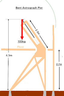
Serious alternatives to a cross axis? A bent, polar [astrograph] pier. The upper section of the pier is bent over. It leans towards the north at the local polar angle of 55°. 

This allows [some] freedom from the absolutely inevitable pier contact of the GEM. Not quite as good as a cross axis but it has advantages. No need for a towering [isolated] pier to support the north bearing of the PA axis.

The main problem is the sheer scale required for the length of leaning pier. It must allow for at least 1m of overlap without any risk of contact between telescope parts and the mounting/pier until very close to the North Polar region. Preferably full sky clearance for all of the telescopes.

My massive, timber and plywood cladding, pyramidal pier can easily cope with such a total redesign. The top section could be made to lean towards the north only above floor level. With the "downstairs" section redesigned to balance the above floor structure's offset. Though the telescopes [and their considerable mass] remain safely centered at the crossing of the mounting axes. Centrally mounted in the dome. To maximize clearance of dewshields under the dome's inner projections. [Zenith board and the slit ribs.]

The existing, pier foundation blocks are spread as widely as possible within the original footprint. With room for expansion to the larger footprint if required. [Very unlikely.] Or even additional foundation blocks if required. Just dig and bury in self-stabilizing gravel. These simple drawings are only suggestions for a basic timber framework. It must be remembered that the base is huge at nearly 3m square. Lateral stiffness is as vitally important as vertical and torsional resistance to flexure.

The upper [leaning] pier section can be made slightly tapered. Or of sufficient cross section along its entire length to clear the telescopes. Sturdy, internal, plywood baffles can help to stiffen the PA "box." I have lengths of steel ventilation ducting which might serve for the leaning section of the pier.

Piers are usually made of heavy, welded steel at the observatory level of commercial mountings. The "bent" or "broken" pier can thus be made to bend at any point. Some astrograph piers rise as a "Z" above the floor. While sitting on a conventional, central pier. This requires very heavy sections of steel for adequate stiffness. Otherwise the bend will act as a leaf spring. It is not usually possible to "cheat" and brace from the base up to the leaning section. This would simply block telescope freedom to pass under the PA axis.

Plywood cladding, over heavy timber sections, just needs extra moment [depth] for adequate stiffness. Plywood and timber are relatively affordable and wide open to design variations and changes. Nor does the home made pier need to be as cosmetically acceptable as a professional mounting. Perhaps costings many tens or even hundreds of thousands. Rather than a few hundred at most. Plywood and timber are also self damping when excited by external shocks.

Medium sized, professional mountings often carry many hundreds [perhaps thousands] of kilos. Mine only has to support around a hundred kilos at most. Managing the length of my telescopes is much more important than their total weight. The moment of all the instruments involved has to be controlled and carefully balanced. Not quite as simple as sliding counterweights along a shaft.

The potential, flexure point of my planned pier is at the bend. It is here that large cross sections and adequate structure are absolutely vital. Compactness of the pier is of lesser importance. Provided the telescopes can rotate around the pier with safe clearance.

The mounting loses its conventional PA, bearing housing. The PA shaft and bearings are hidden inside the sloping pier. While the 50mm, stainless steel shaft is made as long as possible. Length reduces the impact of bearing play. Increased spacing between the bearings improves rigidity. I have some spare 50mm shafts. One of the original Dec shafts could easily become a much longer, Polar Axis. 
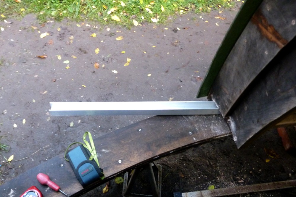
The next stage is to measure the required offset from the telescope mounting plates to the mounting head. A box section pier needs much more room to pass around the corners of the box. As the telescopes rotate around the PA while pointing at The Pole. 

Not that I am ever likely to do so deliberately. Though you never know when a Goto slew won't try to pass close to the pole. My AWR drive system would often try to pass under the pole. Which would have been a total disaster had I not been constantly monitoring its every movement. I could never, ever leave the telescopes unattended during any slew!  Even a routine Home & Park call might do a nosedive into the floor of the NE corner of the observatory!

One particular difficulty with mountings is cabling. Unless all the cables can be passed through a hollow polar axis then they will inevitably run out of length. They will find themselves wrapped around the mounting or the telescopes. Few cables are mechanically strong enough to be stretched. The plugs are particularly vulnerable. 

Should I convert the new PA axis to tubular? I had a great deal on the purchase of the 50mm flange bearings. I'd only need one or perhaps two of much larger diameter. The price rises astronomically with bearing bore. All would depend on finding a suitable length of precision diameter and dead straight, thick wall, steel pipe. My lathe won't take lengths greater than about 18". So I can't turn longer pipes between centers. 

The alternative is a disk based PA instead of a shaft. Though I prefer a combination of both. A disk [or rather cylinder] can provide a very deep cross section at the weak point between PA shaft and flange. I buried the PA, Tollok bush inside a very deep, 180mm Ø, aluminium cylinder. So that the cross section was maximized. 

The Tollok bush expands outwards into the cylinder over its full length. The cylinder itself is bolted directly to the Dec housing over a large radius. Providing massive support at this vital junction. The same arrangement could not be achieved at the more lightly loaded Dec junction. This was due to the narrowness of the double channel saddle. [H-section] Here, the Tollok bush was buried inside a massive brass cylinder. See the image for an earlier set-up with the 6" f/8 H-alpha telescope. A Vixen 90mm f/11 is mounted for solar, white light observation and imaging.


*


21.12.2021 The [near] impossibility of building a second floor, cross axis mounting.

*

I tried imaging mid-afternoon on Sunday 19th. The sun promptly sank below the ridge of the house! If the telescope had been another foot higher it would have been clear enough to capture. Albeit with thermal issues from the warm roof. Given I now have this information I should have built the observatory at least a foot higher. 

I wonder if that is possible with the planned, cross axis mounting? I have been intending to match the axis crossing height of my present DIY mounting. 

Increased height might be worth serious consideration. The new dome should he be high enough for clearance. If not, I could add a riser ring to the top of the expanded building. Is it really worth all that extra effort and delay? I am not sure that it is. 

Then we have to look at the increased demand on solid, but totally isolated support for the north bearing of a cross axis. The observatory is two stories high. Which adds meters of height just to reach the floor. Already 2.7m above the ground. Now imagine a soaring tower to rigidly support the north bearing. A chimney block structure? How big does the foundation block need to be for that? I am beginning to see how colossal the structure would need to be.

I need to be able to hang 2m long telescopes from both ends of the Declination axis. This will give me the ability to use the 10" f/8 for lunar imaging. The 10" would balance the 7" f/12 and 6" f/10 H-a solar refractors. Without needing massive counterweights.

I do NOT want to be remounting individual telescopes once any of them are installed. They are too heavy, too bulky, too fragile and far too awkward for that. Even with a 3x4 block and pulley the job is VERY hard work. It has to be carried out from a stepladder with access to the lifting rope at the same time as I am fixing bolts between the telescope and a huge saddle.

My stainless steel bolts have arrived in the post. Excellent service from Birger and PostNord!


*

19.12.21

19.12.2021 Shutter support geometry.

 *

Sunday 19th 44F, mild but overcast. Forecast to be sunny all day after a clear night.

The next step, in the fitting of the new slides, requires the shutters be raised to their correct working height.  They must also be straight and the ribs vertical and parallel. 

Only then can I fix brackets to hold the new slides to the shutter ribs. One complication is the need for countersunk fixing screws to avoid contact with the skate wheels. 

Some considerable "fiddling" is guaranteed to be required. "Normal" cylindrical shutters would have been infinitely easier to arrange. My spherical shutters have cost me months of extra difficulties.

I am still thinking about the vertical rollers to replace the unexpectedly "fragile" drawer slides at the top. Even assuming that laterally and vertically displaced slides and rollers will work for a normal, sliding gate design. 

Do I need to tilt the steering channel inwards to accept the lateral loads? Are there any lateral loads if the shutters are stiff enough to act as a simple, sloping beam? 

There are certainly twisting forces applied when the shutters are pushed at the bottom. The top slides are well over 2m away measured horizontally. Which may explain the serious problems I had when opening and closing the shutters. There was considerable lag at the top. I would usually have to go outside and use a batten to shove the tops of the shutters. Not ideal when I am supposed to be inside the dome!

Regarding the share of the loads on the slides: It looks as if the lower half has much greater length of material than the upper. [When the shutters are divided equally and horizontally.] A horizontal beam would share the loads equally and each would carry half the total weight. 

In the case of a curved shutter it looks as if the lower slide takes a much greater proportion of the weight. Quite probably 2:1. Which could be an advantage. Since it reduces the flexure loads on the more horizontal upper half of the shutters. Where stiffness is most likely to be compromised. 

With a sliding gate, vertical roller guide, there is no support [at all] at the top of the shutters. All the weight is on the bottom. Should I build a pair of skate wheel slides for the top of the shutters to share the loads? Or carry on with the sliding gate [vertical roller] design? Build the vertical rollers just to see if it works? 

If not, I can use a similar design to the lower slides. Using my older set of smaller, skate wheels. An alternative design would be upright skate wheels in a channel for steering. The upper slide could then share some of the loads. Though at the cost of an extended channel guide rail at the top of the dome. The upper channel would be inverted. So it could not fill with wet leaves like the lower one. 

I found some sturdy brackets and tried to fit them to the slide channels. Unfortunately, the socket head, M8 screws jammed the wheels solid. The heads were simply too large for the space available. So I have ordered some M8, stainless steel, countersunk screws. Which will leave plenty of room for the wheels to turn. 

I have belatedly added an image of the completed pair of bottom, shutter slides. The M8, plain shank bolts were a better fit in the 8mm skate wheel bearings than the M8 threads. The sturdy brackets will be bolted to the shutter ribs. I used the large head, M8, countersunk screws to bolt them to the slides. After countersinking the inside of the slide channel.


*

18.12.21

18.12.2021 And then there were two. [Shutter slides]

 *

 Saturday 18th 46F, leaden overcast.

I finished off the second shutter slide. Shown inverted.[Image right.] I am presently using 10mm nuts as axle spacers. To keep the skate wheels central.

Then I carried both slides out to the dome. To check alignment on the base ring [steering] track. I still have to see how to attach the new slides to the shutters.  Being solid metal the support channels can be hung from simpler brackets. Without the loss of stiffness and lack of "meat" suffered by the former softwood battens. I'd still like to include fine, height adjustment of the slides via screw threads. This may be easier with jack screws lifting the steering channel. Provided they clear the rotation roller track under the base ring.

Here is an available light image of the shutter slides resting in the steering channel. I wanted to bring out the laser level lines. These are being projected on the upper edge of the base ring all the way around the dome. 

The vertical line follows the gap between the shutters. To confirm they are vertical where they meet.

The base ring [steering] channel cannot go any further away because of the inner, shutter ribs. The channel needs to be about 20mm further out. This will allow narrow, angle brackets to be bolted directly to the shutter slide from the outer ribs. 

I rather like the clean look of the new skate wheel slides. I have more M8x60mm, A4 stainless steel bolts on order. To form the skate wheel axles. I have ordered both screws and plain shank bolts to see which is best. The M8 thread size is slightly undersized in the 8mm wheel bearings. I'm hoping that the plain shanks will be a closer fit. 

I have also ordered plain and Nyloc M8 nuts in A4 stainless steel. I can use these nuts to preload the skate wheel bearings. Both to resist tipping and to fix the centering of the wheels in their support channels. There is absolutely no point in wasting money on flashed zinc hardware. Which rusts before it is placed in the [daylight robbery] retail bubble packs. Trying to dismantle assemblies, once rusted, is a further waste of valuable time. I grew sick of rusted fixings when I was a keen cyclist.


*

17.12.21

17.12.2021 Another shutter slide rethink. KISS!

 *

Friday 17th 41F, heavy overcast and thick mist. No chance of any imaging today!

I have decided to simplify the skate wheel support for the shutters. Making pivoted bogies would drastically shorten their effective wheelbase. Perhaps leading to tipping of the shutters. My desire to spread the load between more wheels can be achieved by accurate placement of the axles on a straight line. The flexure of the tires can even out the loading between four wheels. 

It works for hefty skaters. Wearing inline skates for repeated aggressive maneuvers. Rollers skis have only one wheel at each end. So they will probably work for my humble, dome shutters. 

A closely spaced pair of wheels, at each end of the inverted channel, will do the job. Being so close together will reduce the differences in wheel loading between pairs. 

I shall cut down the 50x200mm box section to make 100mm deep channels to hold the wheels firmly. 

Or not. I found some 50x140 box section hiding in my scrap heap instead. Which made more sense than the 50x200.

The DeWalt "Metal" jigsaw blades were a complete waste of time. I mixed lamp oil with light "cycle" oil and adding copious quantities the fine toothed, saw blades. Still they became worthless in seconds as they built up aluminium in the teeth. So I looked for alternatives in my shrinking stock of [short] jigsaw blades. Standard length blades hit the inside of the box section on the out stroke.

Straight toothed "Laminate" blades worked really well. These have an aggressive, staggered, tooth form of different tooth lengths of medium pitch. 

I used a medium speed on the saw and sloshed the lubricant along the cut line and in the cut slot as I progressed. Half an hour later I have two 70mm deep x 49cm long channels. 

The second image [Right] shows suitable spacing and axle depth in the channel to provide clearance.

The cut edge was typically wavy for a sloppy Bosch jigsaw. These edges will be straightened by filing or sanding. The mock-up shows the "axles" resting on the cut edges. In practice the axles will be securely clamped through holes in the channel webs. With spacers to load the bearings against tipping. 

I used the profile's extruded back edges. Rather than the wavy, freshly cut edges for all my measurements. Once the wheels are fitted they will become completely invisible. Being hidden by the nested channels. A test run proved that the slide's rolling movement was silent, friction free and smooth. I must hope the same holds true once the wheels are mounted on their axles.

 The third image [Above left] shows the channels drilled and the wheels mounted on 8M x 60mm stainless steel bolts. The assembly is inverted in this view. The bottom channel, in which the skate wheels run, fits inside this channel with room to spare.


*

16.12.21

16.12.2021 AR2907, 8 & 9

 *

Thursday 16th 41F, otherwise clear but with a bank of cloud across the low sun. 

10.30 [CET] Still waiting for the sun to clear. Optics dewed again. Dew bands on full. Removed D-ERF cell and blasted this and the objective with the hair drier.

10.41 Sun still obscured. The neighbour's tree is blocking the sun too.

11.32 [CET] First [poor] image of chain of spots. It has taken this long to clear the dew. Image shaking with thermal agitation.

12.18 [CET] Removed the intermediate IR/UV protective filters. Demisted the etalon. It was soaked in dew. Small, soft spot of dew still left on the objective. Violent HF thermal agitation. Soft image.


12.38 [CET] No protective filters. [Just D-ERF] Mono16 capture. The ARs are very active with lots of flaring. 


Paused at 13.00 for lunch. The image would not sharpen. The sky looks misty white around the sun.

13.30 Sun is just above the house roof. The seeing has not sharpened at all. 

14.00 I tried as many different things as I could but there is no improvement in image quality.

I'm giving up for today.


*

15.12.21

15.12.2021 AR2906, AR2907 & AR2908

 *

Wednesday 15th 46F, overcast, then cloudy then cleared enough to trick me into trying some imaging. 

 11.27 SE quadrant. Poor processed image captured through fully dewed objective. Two dew bands on full around the D-ERF and objective cell. Foam "dewshield" in place. Hair drier had no visible impact.

 11.50 [CET] Cloud has arrived at high speed from the west.  Fully overcast in seconds! Dark enough to rain! Closed the shutters just in case.

 SharpCap update. 4.0.8395. License has expired. Paid £12 for Pro version.

SharpCap offers ASCOM mounting control. ASCOM tells me there are no COM ports. I get a single flash from the serial adapter when I connect it but it hasn't flashed rhythmically for a year! I have tried all the USB ports available. Mostly USB3.


*

14.12.21

14.12.2021 Shutter slide materials.

 *

Tuesday 14th 41F, early cloud eventually cleared to watery sunshine. Brighter still after 12.00. I had a look at the sun in the 90mm with Lunt wedge. One spot was visible in the cloud dimmed image. The plywood dome is growing tiny mushrooms all around the base ring!

I gathered together my scrap aluminium, box profiles to see what can be done. Apart from the 35mm channel I have useful lengths of 50x200mm, 70x70mm, 100x200 and 120x120mm. All external dimensions. Length-ways cuts can convert these box sections into useful channel sections.

The 50x200mm can become the bogies when cut along the middle of the longer dimension. To form deep, but narrow channels. The skate wheel is shown within the various profiles for scale.

The 70x70 profiles can be channeled to house the bogies. With the 120x120, again cut into channels, to support the whole lot and connect solidly to the shutters. Having a middle sized profile will allow fine screw adjustment for level and height. The shutters are very sensitive to these parameters. I am saving the lengths of 100x200mm for the planned, cross-axis, English style, equatorial mounting.

Axle clearance is an issue which needs careful consideration. Skate wheel axles use flat headed screws into a central, axle unit to avoid protrusions. I may be able use this system to advantage. All of these channels offer reasonable, lateral clearance between each other.


*

13.12.21

Shutter slides rethink 2: Upper guide rollers:

 *

I have had time to think over the options for skate wheel slides.

Mounting the support slides at the top would put all the loads on the dome at the worst possible point. The top of the dome has the 1m wide cutout for the observation slit. Despite being framed by the ribs and zenith boards I prefer the shutter loads to be taken by the combined, fourteen, rotation rollers under the base ring.

The vertical guide rollers at the top will sandwich the shutter top boards. These upper guide rollers will be on the outer edges of the shutters. At the strongest point of the ribs. Channel stops will catch the shutters and hold them firm both when open and closed.


*

12.12.21

12.12.2021 Shutter slides rethink.

 *

Sunday 12th 36-39F, overcast with a rainy morning. Indoor homework on shutter slides.

 I have been watching YT videos on sliding gates. Hoping for inspiration and increasing my options. Very useful they were too. Most gates rely on a single pair of vertical rollers sandwiching the top of the gate. I can use this system at the top of the shutters. Support being only at the bottom of the shutters. The channel providing the steering. Much like grooved rollers on a rail. 

 This removes the need for fragile drawer slides altogether. They had been a worry. How would I work on the shutters once the dome was lifted well out of reach? While a ladder can be erected on the observatory floor I can't easily support the shutters. Not if needed to remove the drawer slides. Lots of tiny wood screws were completely hidden from view! 

It needs the robustness of solidly mounted rollers. The present difference in friction and shutter flexibility has made opening and closing a real struggle at times. The drawers slides are visibly being twisted. They were never designed to cope with such loads.

 Adding more, inline skate wheels, to spread the load more evenly at the bottom, needs more thought. It really needs pairs of wheels mounted on pivoted "seesaw" bogies. This would ensure all wheels are in intimate contact with the bottom channels. Rather than only two of any four wheels taking all the loads. 

There is a possible downside with bogies: The pivots are well inboard of the outer margins of the shutters. Which might allow them to tip if the shutters are pulled or pushed from higher up. This [potential] rotational force might be precluded by pulling on ropes at the very bottom of the shutters. It is difficult to reach much higher from the observatory floor anyway.

 I have some scrap, 50x200mm [2x8"] aluminium box section. Which could provide deep channel, seesaw material. In sturdy cross sections once suitably sawn to size. The resulting, channel sections would support the skate wheels from both sides. Nesting the channels [see rough drawing] may provide enough clearance. 

*

11.12.21

11.12.2021 Matching the dome diameter to the base ring.

 *

Saturday 11th 36-39F, heavily overcast cold, grey and damp. Some brief, golden sunshine in the mid-afternoon. 

 I spent the morning in the new dome. I had been struggling to get the shutters to close together. When I measured the distance across the dome's original, arched doorway, at ground level, the gap was 8" too much! The shutters were also 10cm too low above the base ring. So that the shutters were not concentric with the dome.

 All my shelf brackets had been fixed with a deliberate drainage gap behind the base ring. To let internal condensation pass unhindered down to the skirt. Which would hopefully, allow it to drip off. Rather than puddling on the base ring.

 Today I fitted some angle brackets to some of the shelf bracket fixing bolts. Then tensioned ratchet straps between them across various chords of the dome. Eventually the gap behind the base ring shrank. The gap across the doorway was now down to within 10cm of the original measurement. 292cm instead of the required 282cm.

 I had to the loosen the fixing bolts to ease the shelf brackets upwards after removing the fixing screws.  The problem seems to be the base ring being too close above the dome's moulded, reinforcing ring. Which runs around, just above the skirt. Th GRP moulding had lifted the base ring and pushed it inwards. Preventing the ring from touching the inside of the dome. Consequently the dome was forced outwards. Making it larger than the outer, cut radius of the plywood base ring. 


*

3.12.21

3.12.2021 Mitre saw: New dust collector guides and hose.

 *

Friday 3rd. 34F. Overcast. I haven't done a thing on the dome for days. Snow, gales and continuous rain don't allow me the freedom, nor desire to do much outside.

I have discovered some useful ideas for containing the aluminium swarf flying off the miter saw blade. One YT poster has cleverly used rubber sheeting to guide the swarf to the back of the saw where he uses a workshop vacuum for wood dust. 

I'd prefer to guide the metal swarf into a container beneath the saw stand. As his guides are attached to the saw they aren't affected by the saw being angled for miters. 

 https://youtu.be/viRRYmIfzC8

Many of the rigid box ideas on YT simply won't fit into my shed. I have lots of heavy, rubber, pond liner I can use for the swarf guides. It took me ages to tidy up the swarf last time. It sprays literally everywhere at very high speed. Worse than that, it has much more weight than wood dust. So gains momentum as it is accelerated by the teeth of the blade. One slight worry is the flammability of aluminium dust.

First I removed the DeWalt, dust collection, plastic tube from the saw. Then discovered that a 60mm corrugated hose would just about slip through the triangular cutouts in the saw castings. The original tube is tiny. A smooth bore, 65mm hose would probably just be able to go through the saw. Though it would require the hose was made triangular to fit. 

An alternative would be 60mm PVC, gutter down pipe. This would need to be warmed with a heat gun to make it fit the triangular openings. Getting it back out after it has cooled might be a real struggle! Note how the sliding mechanism distances the blade from the collector. [Two lower images.]

The main problem with changing the extractor pipe to a larger one is the blade fence latch. It is bulky and lowers directly into the path of any extraction system. Total idiocy on the part of DeWalt designers. I use the term "designers" loosely.  

A screw top cleaning fluid bottle would make a good directing funnel. It would have to be slotted for the saw blade and a cutout made for the fence latch. Even so, it would be several orders of magnitude larger than the original collector area. Which blocked continuously in normal use. 


I am still trying to discover the real purpose of what I have mistakenly called the "fence latch." It has no connection to the saw blade or its protective shielding. DeWalt calls this thing a "rear guard" in its spares catalogue. Does it prevent kickback in a jam? It seems not to have any spurs to prevent kickback. Its removal would certainly simplify my collection funnel ideas. 

It is hinged and lightly spring loaded. Yet rides well above any material being sawn. I found a reference to it on a forum where a user had a kickback and destroyed this "rear guard." Other than it having been modified at some point I haven't discovered any more details. My wild guess is that it is a shield for the exposed part of the blade but little more. Though that doesn't explain the hinge or return spring. 

UPDATE 6.12.2021: A long experienced, woodworking machine repairer has warned me to leave the rear guard in place. It catches small pieces of wood which occasionally splinter off the item being sawn. This prevents them from being caught in the blade and flung around. He shared dire warnings about bloody stumps of fingers and thumbs. Being found in machines returned for repair after an accident.  

I was further advised that a larger, dust collection hose will just slow down dust collection by reducing air velocity. My crude DIY collector wasn't properly aligned with the saw blade exit anyway. So would probably not work as desired. If the saw were fixed, rather than sliding, it would have been far easier to guide the swarf into a container. I'll have to look again at outer rubber shields to help contain flying swarf.


*

30.11.21

30.11.2021

 *

Tuesday 30th 39-41F. Gales and light showers.  

The new, miter saw blade has arrived. With 100 of the usual hard point teeth it is intended for aluminium and other soft metals and materials. I had a nice discount because of Black Friday Sales.


*

28.11.21

28.11.2021 New ALU miter saw blade.

 *

Sunday 28th 36F, cool, misty with misty rain. 

I have ordered a new, discounted, aluminum cutting blade for my 12" DeWalt, miter saw. It is the only way to sensibly manage the 120mm square tube. 

I will need to cut even larger, aluminum, box tubing for the new, cross axis mounting. Up to 4"x8" sections are waiting in my neatly stacked, scrap pile. There is no way to cut these absolutely square without wasting countless hours on truing up skewed cuts.

Which was what I did with the last mounting. Lots of 10mm plate was cut with a Bosch jigsaw and lamp oil. The Bosch wouldn't know a straight line if it met one. Sanding edges square on aluminium is an exercise in frustration. It takes forever and the sanding material clogs almost immediately. I even bought some carbide disks for the angle grinder but the coarse grains loaded up to useless in no time.


*

27.11.21

27.11.2021 Channel section shutter wheel supports.

 *

The box section tube turned out to be 120x120x5mm. Which is fine. I marked up a 49cm length. It will be parted length-ways after cut-off. I only managed to square one end with the jigsaw and a new, fine tooth, metal cutting blade. It was slow work despite trying lubrication. The teeth of the blade soon loaded up while using light oil. So I dug out the lamp oil ready for the next step. 

A coarser toothed, aluminium blade would be better. The fine teeth and short blades are probably intended for mild steel. They clog too easily in the softer metal. I could use the miter saw but it makes a hell of a mess! The blade is also much thicker. Which wastes material unnecessarily. An ordinary hacksaw is so slow in 5mm wall thickness aluminium that it would be foolish to even try. A slow turning, cut-off saw would be ideal but economically unrealistic.

Rain in the afternoon stopped play.

*

25.11.21

How to properly support the shutter wheels?

 *

Thursday 25th 42F. Rainy start. Still very dark at 08.00.

Yesterday I spent some time fiddling with the new skate wheels on the right shutter. I kept adding spacers to make the shutter concentric with the dome. A couple of 10mm nuts outside the wheels was all it took. The problem was an increase in cantilevering of the wheels on the extended axles.

Properly supporting the wheels has become the latest hurdle to overcome. Do I need a channel of some kind to reach over the wheel without being too bulky? I looked at using brackets from the ribs at the side but the geometry is all wrong. Everything I add has to, quite literally, pass through the slit ribs. Which means cutting more rib away. 

I could make a much more sturdy axle with the 8mm bolt as an extension. Then all I have to do is fix the axle immovably to the shutter. No idea how that would happen.

A really stiff piece of angle could be fixed to the shutter bottoms to support 8mm, stainless steel bolts as axles. The plain shank on bolts is larger than the M8 thread. Reducing the present, excessive slop. Clamping the bearings lightly with the provided middle spacer will increase load bearing.

Making the angle profile the full width [and depth] of each shutter would add greatly increased stiffness. The wheels could then be properly supported from only one side. 

A third wheel in the center of the shutter would help reduce the cantilevered and local loads on the other two. Four wheels even more so. I have eight!

I quite favour this idea. Though it needs the shutter, bottom boards to be beefed up and properly fixed. Or completely replaced. I am presently using off-cuts from 2x4 softwood. Not ideal as the wood can't resist localized loading from the foolishly extended axles.

The angle profile, wheel support could be bracketed directly to the shutter ribs. I still need to bridge the curved [highly asymmetric] gap to the GRP shutter covers. 

Up to this point I haven't fixed the covers to the bottom boards. Relying instead on the multitude of brackets fixing the covers to the shutter ribs. The softwood bottom boards were only temporary to see how things progressed. They were only put there to hold the drawer slides. Which have proved to be completely inadequate.

If I can find aluminium angle profile wide enough I can shape it to reach out to the GRP covers. Then I can bracket to the covers as well as the ribs. Allowing the use of the matching 10mm bolts where they are visible on the outside of the shutters. Which way up for the angle profiles? They could have the open side up. To allow easy access to the axle bolts. This is all beginning to take proper shape.

Now I just have to find two, sturdy, angle profiles nearly 60cm long. It looks as I shall have to cut up some of my [scrap] 5"x5" aluminium, box section tube with 5mm wall thickness. To make two, very wide, angle profiles. I was saving this material for the cross-axis mounting. If I can't complete the dome I won't need a new mounting!


*

23.11.21

23.11.2021 New skate wheels arrive and poor imaging again.

 *

 Tuesday 23rd 41F. Bright start but with some cloud. Mostly thin and high.

10.00  Optics dewed again. Though it wasn't so cold last night. 39F. I removed and dried the D-ERF with the hair drier. Remembering to shield the objective from direct  sunlight. The I turned the telescope  away from the sun while I warmed the objective. Both dew bands on full. The D-ERF blocks the sun's warmth to the objective which might otherwise help to clear the dew. 

10.30 Thin cloud obscuring the sun. Making the sky white. Using the 1.6x GPC for wider field of view for the large, southerly filament. Far too much gain needed even at 10m/s exposure. [200] No useful image so far. 

Now my neighbour's tree is rocking over the image! I have set the telescope almost vertical to warm in the sunshine. I can feel warmth on the woodwork in the dome. So there is some solar heat to be gained. With the objective at the top I'm hoping for some chimney effect.

I kept capturing new videos but the images were spoilt by the thickening cloud from the NW.

13.00 I have fitted two larger skate wheels to the right shutter. It rolls far better but the wheels need much better support and from both sides. The wheels are leaning over with the long, cantilevered bolt into the bottom board. 

Being so "grippy" the rubber is dragging as it rubs against the channel. I thought I was missing something obvious but the "top hat" spacers were for 6mm screws. I am using 8mm bolts which match the bearings. I am wondering if I can use large metal or plastic  spacers to keep the wheels upright. 

I had to trim the slit ribs to allow the larger wheels to pass. Then trim the bottoms of the shutter ribs so they didn't drag on the channel. The bottoms of the shutters need to be lifted, pushed outwards, or both. They aren't concentric with the dome. The gap is smaller at the top of the original door height.

13.05. Full overcast has arrived. Time for lunch.

Heavier cloud in the afternoon with a shower at 16.00.


*


22.11.21

22.11.2021 New skate wheels and dewing.

 *


Monday 22nd 31-41F. White frost. Early cloud clearing to bright sunshine. I have my Kamik winter boots and winter clothes on.

I have ordered a new set of bigger wheels for the shutter slides. 84mm Ø in the cheapest inline skate wheels I could find. In a set of eight including bearings. These should provide plenty of axle clearance over the aluminium, channel walls.

I also ordered more 60mm Ø skateboard wheels to match the steering rollers on the plywood dome. The number of rollers on the bigger dome rises to 14 from the previous 8. Hopefully the increased number of steering rollers will help to maintain concentricity of the larger dome on the bigger building. See the image of the rotation and steering roller combination. Including aluminium security disk against lifting.

As usual, after a cool night, the optics were dewed. I put both heat bands on full without effect. I have now wrapped the forward section of the main tube, behind the objective, with layers of closed cell foam for insulation. Leaving the last few cm bare to hold the heat band.  

After heating from 10.00-13.00 and using the hairdrier frequently, there was still a 3" diameter dew spot on the objective! Which causes appalling images! The dew scatters light and ruins the sharpness. A wasted three hours of idiocy and optimism!

I have left the telescope at right angles to the sun to warm up over lunch.

14.20 Image of large southern filament shows the dew has cleared. The the bare sections of the main tube felt luke warm to the touch after an hour. 

Now the sun is dragging itself along the ridge of the house. Mushy and wobbling image on the monitor. I am unlikely to get a better image than the first after lunch. I didn't. Another hour wasted.


*

21.11.21

21.11.2021

 *

Sunday 21st, sunshine promised but very cloudy. Coming from the west then north west.

I trimmed the ribs to provide clearance from the skate wheels and base ring. Skate wheel axles still dragging on the channel. I haven't reached the shops to buy a plastic filler strip yet. 

Or, I could buy some larger inline, skate wheels. Those I have now are 72mm and cost small change secondhand. While 84mm would give me 6mm increase in radius. Ensuring plenty of axle clearance over the channel walls. 80mm is an option but that would be only 4mm clearance. Which might be too tight. Ironically, a couple of strips of 30mm x 5mm plastic from the DIY store would cost the same as 4 wheels including cheap bearings.

10.00 Tried imaging but very cloudy. Optics dewed. Particularly the objective. Have 2 heat bands running flat out. [90F.] Repeated blasts with the hair drier. No obvious change so far.

Two widely spaced, small sunspots. A large, S-shaped filament in the south. Soft and useless images as it approaches 12.00. Becoming even cloudier. Still dewed. Giving up.

Showers in the afternoon.

*

20.11.21

20.11.2021 Skate wheel shutter slides continued.

 *


Saturday 20th 50.7F, damp with a leaden overcast.

I made very little progress yesterday. The inner shutter ribs are obstructed by the base ring. If I cut away the ring I lose its strength. 

If I cut away the shutter ribs they could end up at half mast. If they remain as is the shutters wont close without being lifted bodily. Which throws the support off center.  Leading to laterally leaning shutters.

Another mock-up. I drilled the bottom boards 7.5mm and screwed in some long bolts to hold the skate wheels.

The shutter ribs are resting on the channel and base ring. Rather than the wheels. Which makes far too much friction. I still need to get to the shops to buy some plastic strip to place in the channel. This is to raise the axles clear of the channel.


*

19.11.21

19.11.2021 Skate wheel shutter slides cont'd.

 *

Friday 19th 53F.  Another grey day with a heavy overcast. 

I notched the bottoms of the slit ribs to allow the skate wheels to pass unhindered along the channel. The shutter, bottom boards were freed from their brackets. This allowed them to be raised to a better position. 

I may leave the top drawer slides in place. Relying on the robustness of the lower tracks to achieve better alignment. There is very little room up there for the channel and skate wheels to fit between the boards.


*

18.11.21

18.11.2021 Skate wheel shutter slides.

 *

Thursday 18th 46-50F, leaden overcast with rain promised. It started at 10am and hardly paused.

Yesterday afternoon I notched the ribs enough to be able to thread the channel rail into position. The extension beyond the base ring can be seen in the first image. Not too extreme. The rail is cut rather long. To avoid it being too short if I need to add support beyond the run of the skate wheels.

First I aligned the rail to within a millimeter of the double, plumb line level using the laser rangefinder. [Repeated readings to confirm] Then marked the base ring to ensure it stayed that way.

The left shutter [seen from inside the dome] nestled perfectly against the channel. While the right shutter was badly skewed. [See second image] The right shutter seems to be rotated anticlockwise in plan.

It has occurred to me that the individual top drawer slides may not be parallel. The screws have started pulling out. A single, channel, top rail will guarantee they are both straight. Though not necessarily parallel to the lower rail unless I make it so.

There is also the matter of the height of the tops of the shutters when converted to wheels and channel. Will this change the height of the lower shutters? Perhaps I should concentrate on the upper rail first? I have to introduce the wheels between the shutter top boards and the dome zenith board. This is bound to affect the lower shutters. It might be risky to expose the shutter wheels to the weather on the outside in the long term. So it is arguably safer to have them positioned internally. Shame it is raining again! 


*

17.11.21

17.11.2021 Shutter track positioning.

 *

Wednesday 17th 41F. Leaden skies with rain this morning. 

Image shows the new top track resting on top of the dome. It cannot go any lower without cutting into the dome. Photographed at dusk. The pipe insulation continues to work well in protecting the dome from abrasion by the ladders.

Having converted to channel profile tracks raises a number of issues down at the bottom. Channel positioning is both optional and critical. With many positives and negatives arising from different choices. 

I plan to have the skate wheels inboard of the shutters' timber, bottom boards. The wheels and tracks are three times the thickness of the [soon to be discarded] drawer slides.

Outboard: The further away the lower channel rests, from the center of the dome, the more exposed it is to the weather. Channel support from the base ring reduces with greatly increased cantilevering at the ends. Sturdy support will have to be found from beneath the base ring to support the heavy shutters. Leading to potential conflicts during rotation.

Inboard:  Bringing the channel inboard, nearer the dome means I have to avoid the inner edge of the base ring. Otherwise my storm anti-lift restraints become blocked. Which would prevent the dome from rotating. I do not favour manually operated latches. It is far too easy to forget them. So I have permanent latches always at the ready in case of storm. I used heavy aluminium disks in the case of the plywood dome. These have worked effortlessly for several years.

A more inward, channel position, provides much more support from the base ring. With considerably shorter overhangs beyond the outside of the base ring. Leading to improved cosmetic appearance. Which are all major positives IMO.

The bottoms of the slit ribs will have to be heavily notched. To clear both the fixed channel and the 72mm Ø moving skate wheels within the track. 75mm + clearance above the base ring. Making oversized notches in the wrong place would be a nuisance. Weaken the rib junction with the base ring and probably end up looking horribly untidy. 

The problem is that the slit ribs have to be notched somewhere. To allow me to play with different channel positions. There is presently no room to slide the channel under the bottoms of the slit ribs. So I have chain drilled suitable notches and will use the DeWalt multi-tool to saw out the notches. 

Despite the high cost of DeWalt saw blades the latter is proving poor at plunge cuts into Baltic Birch ply. I upgraded to a Titanium coated blade. It soon wore out with only very occasional use. The "ordinary" quality DW saw blades soon wear their teeth down to a smooth stump. Not what I'd call a professional quality tool at all. Though the vibrating multi-tool does have unique advantages. Particularly where no other saw can be brought to bear in a tight corner. The sanding qualities with the small, Velcro attached, abrasive pads are quite pathetic. 


*