31.1.20

31st January 6" f/10 H-a telescope all but finished.

*

Friday 31st overcast 44-46F. The post brought the new, M5, stainless steel collimation screws and [A4 SS] T-nuts.
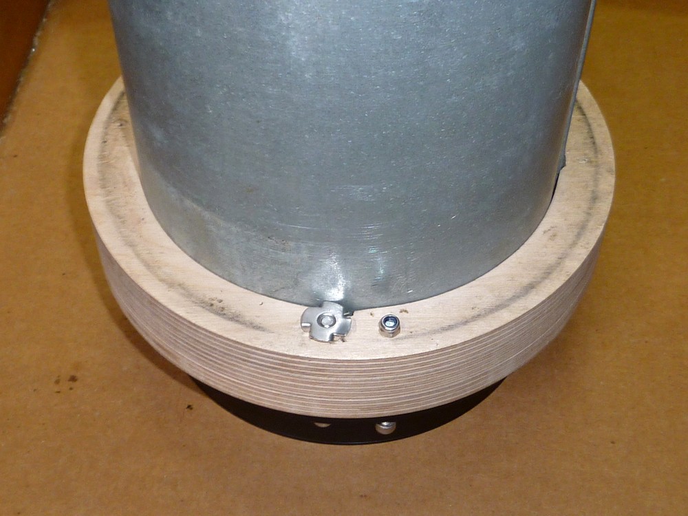
The laminated plywood counter cell proved to be far tighter on the main tube than I had imagined. I had the main tube standing on its flange on a heavy concrete slab. While I used a 2x4 as a pile driver to wallop the ring down the tube.

A plastic ring protected the plywood ring surface. It must have been at least 20 minutes before I reached the "business end." The flange finally sank into the recess and I could relax. Lunch time!


I made rapid progress this afternoon. I have the lens mounted on the tube. I used smaller M4 screws to hold the rings together. The heads have been flattened with a file to act as pressure pads for the collimation "push" screws. Nyloc nuts on the back of the rings will avoid loosening.

The tube rings are ready to be attached to the saddle on the mounting. With unused "machine feet" acting as thumbscrews with their shanks relieved to allow the rings to be clamped. The images show the details. The tube rings were rated for 160mm but the main tube was 162mm OD:


The tailpiece matches the one I made for the Celestron 6" f/8.

The alloy ring is a clamp for the 2" WO extender. Three screws clamp the extender while three screws hold the clamp to the tailpiece. Now fitted with much shorter screws counter-bored into the plywood tailpiece. I had threaded the holes in the ring so the nuts, in this earlier illustration form yesterday, were completely unnecessary.

With the addition of the PST etalon and filter stack the new telescope is almost ready for use. The only thing missing now is internal matt black painting and a baffle system. Oh, and the D-ERF and holder which I returned to Telescopes Express two weeks ago. That was because the filter would not fit into the holder! I haven't heard anything since they confirmed the returned items were received. Reminder email sent!

*

29.1.20

29.02.2020 Sun? What sun? Got dew though! AR2757!

*

Wednesday 29th, 41F outside 43F inside the dome. Max solar altitude about 17° today.

10.30: Rather overcast with some teaser blue patches, except where the sun is. Managed to briefly center on the AR in NW quadrant just above the solar equator. Then left the drives running.

Opening the dome to expose the 6" produced a dew haze on the back of the rear element. So now was my chance to wrap two, new dew bands around the objective cell and base of the dewshield. I have a longer Kendrick and an Astrozap connected to the HitechAstro controller. 

No effect on the dew after ten minutes. Turned up the control knobs to "ten past." Bands just beginning to feel warm inside now. 

The Sun is completely obscured by cloud now. Though it hasn't seemed to make any difference to internal dew before today. Even when it was bright and felt warm on my face. The dew circle is just beginning to shrink very slowly. Another ten minutes and the spot is still shrinking slowly but the doublet, lens gap is now steamed up!

I need to buy another power strip of sockets! I have eight plugs connected now. None of them is a big drain but they all need connecting. AWR drives PS, dew heater PS, focuser motor drive, etalon motor drive, lights, computer monitor, laptop charger, LED desk lamp, so far.

It's all a mess of wires dangling all over the mounting and desk. Some of it needs to be within reach of the USB3 strip. None of the little boxes of electronics has an eyelet or any other device for hanging. It has to be a zip tie or hanging from the connected leads.

Sun teasing again through the clouds! Capturing 1000 frame videos 800 x 600 of the sunspot. 1.2ms. 640x480 420+fps at 1.0ms. Lots of smaller dark spots to the south. Quite stable seeing when the sun is visible but thin cloud constantly drifting across the image.

13.20 I'll leave the dew heaters on over lunch to see if it clears the fogging between the objective elements. I badly need to warm up myself! 46F and breezy in the dome. I forgot to put on my old, down jacket.

15:00 Back in the dome but I didn't rush back because of the cloud. Now wearing two down jackets instead of none this morning. Salopettes plus snow boots complete the wardrobe. The heater bands feel warm on the outside. Interstitial dew now gone. Captured some proms in a brief flash of sunshine. Rainbow artifacts are from overdoing it in PhotoFiltre.

*

28.1.20

28.01.2020 Dew heating bands and new tube rings.

*

I was losing so much precious imaging time to dewed objectives, that I decided to invest in combating the problem. While the secondhand hairdrier works well on the front of the lenses it had zero effect on the rear element. I was spending half an hour on full heat warming the objective cell area. So I bought two Astrozap heating bands. One of 6" and one of 7" plus a 4 port HitechAstro controller. The controller came with a cigarette lighter plug. So I also had to buy a 12V 5A PS with cigarette lighter socket.

It all seemed to work. Though the heating effect is very subtle and slow to build up at half max setting on the control knobs. No heat at all from the bands at 1/4 setting despite the red LEDs being brightly lit. The Astrozap bands are both generous in length. As were the cables with each component.

I'll leave it all on at half way and then try it on full to see if things get warmer over a longer time.

5 minutes later: Full on does feel warm now. The heating effect is very centralized on the internal, plastic band. Presumably the outer band will insulate the heating area from the cold air. So this will help to contain and spread the heat. I can only just feel some warmth in the middle of the inner, plastic strip at a 10-to setting.

The 160mm Skywatcher tube rings turned up in the post. These proved to be too small for the thumbscrews to meet properly when wrapped around my 162mm OD main tube. So I had to clamp the joints with setscrews instead of the original chrome knobs. The tube seam fitted at the ring opening. I used stainless steel, hex socket head screws but longer thumbscrews would be far more preferable. One doesn't want to be messing about with Allen [hex] keys when a telescope is dangling from open tube rings high above one's head!

The thread near the screw head needs to be relieved to work properly. You can't tighten something together which has a thread in each half. This is why the original thumbscrews have a smaller, plain shank below the enlarged head. This necessary freedom in the shank also allow the screw to be self-aligning as the two, ring halves close together. The larger, threaded section also maintains captivity when the screw lies only in one half of the ring.


 *

Main tube: Pt.4 Countercell completed.

*

Tuesday 28th: Overcast with rain, on and off, all day.

Continued smoothing the cell now it has three laminated rings. It wants to be tight enough to grip the tube while not being so tight that it causes damage. Nor jamming while the counter cell  is being slid along the entire, 120cm length of the main tube. 

The recess in the front ring worked well. Leaving the rear of the lens cell flange just slightly proud of the counter cell. That means there is enough of a rudimentary seal with the main tube in normal use. Without compromising the small movement required for collimation. Which might have broken the desired seal.

The collimation screws, shown here, are too long but all I had available at the time. I will also need to order some M5 T-nuts for the back of the counter cell. To ensure there is no rotation of the nuts during collimation adjustment. The spikes on the T-nuts will dig into the plywood on the back of the cell to lock the nuts safely into position. I have loads of larger T-nuts but no more M5.

The plywood counter cell will sit immovably, surrounding the front end of the main tube and stopped by the small tube flange. With the front ring slightly projecting while carrying the objective lens in its cell. This objective lens, support system was used on the 7" refractor and it worked well. While safely avoiding the need for a turned aluminium counter cell with unwanted, extra weight and quite possibly, considerable expense. An aluminium dewshield will fit over the plywood adapter ring.

Next, I must make a tailpiece for a 2" screwed [WO] fitting. I shall "borrow" the existing screwed fitting from the present, 6" f/8 as it will no longer be needed. Perhaps I had better start looking for a suitable saucepan to fit over the tail end of the new telescope for a cosmetic lift? I also need to think hard about a truss support for the far end of the PST etalon/filter stack.

I'm thinking about using a finder alignment ring for the tail end of the stack. Only an open truss will provide the necessary hand clearance for adjusting the filter stack. Though I shall, of course, use the existing motor drive to the PST etalon and arrange motor driven focusing for the helical focuser. The latter needs an independently mounted motor to avoid the belt running off the moving focuser drum. I can probably fix the focuser motor to the truss or a suitably placed, support ring.

I have ordered some shorter, M5, stainless steel, hex socket head bolts and ss T-nuts for collimation. Shortening bolts and screws is time consuming and fiddly. It also denies access to the longer item if needed. So I'll add the longer bolts to my stock containers and have them handy in future. If I calculated my lifetime's collection of fixings at bubble pack prices I'd be a millionaire!

Talk about a license to print money! Them! Not me! Even with added postage it is far cheaper to buy such stuff online from specialist dealers. I try to buy stainless steel whenever I can. Mild steel and flash plated fixings begin to rust before they are out of the pack. A total waste of time and money on anything exposed to damp air or the night sky. The price is no higher for stainless steel online than the rip-off, decorative zinc, bubble pack rubbish in the DIY outlets.


 *


26.1.20

Main tube Pt.3 Objective cell adapter [counter cell.]

 *

A single front ring will be bored larger to fit the rear of the objective cell at 168mm. This will help to support the weight of the heavy cell and objective glass. As well as sealing it more effectively to the main tube. 

With the bore being very slightly larger than the tubing flange I can glue the front ring to the others to make a more solid unit. If the bore were any smaller it would catch on the flange as the adapter was slid backwards off the tube. Which would trap the adapter on the front of the telescope. I might want to work on the adapter for some reason in the future. So it would be easier If I didn't need to destroy the adapter just to remove it from the main tube.

The three rings can be turned smoothly on the outside. Once they are glued together while being aligned and clamped together on the telescope tube. The images show progress producing two tightly fitting, adapter rings on the lathe. They were too large for the 4-jaw chuck. So I had to screw them, from the back, to my largest faceplate. I doubt they need to be quite so tight. So I will sand them to tidy them up.

Whoops! Re-measuring the flange made it larger than the rear cell diameter. The front ring will have to be screwed to the rear rings. Or, I file [or grind] the tube flange smaller. This would allow the three rings to be glued solidly together but still removable from the tail end of the tube. I want to smooth the exteriors to match each other once glued together. To look like a solid object once painted. I must remember to cross the surface grain of all three rings to avoid warping over time.

Sunday 26th. Another grey day. Third [front] ring completed to fit over the rear of the 168mm iStar 150mm objective cell. The two front rings have been eased by sanding and then glued together while fitted onto the tube.

Yet to decide whether I want to reduce the tube flange slightly and glue the front ring to the other two. Or screw the front ring to the other two with machine screws. There is only a few millimeters difference in diameter between the flange and ring. So it's not much work. I'll think about it over lunch. Sudden sunshine at 13.30!

I have decided to reduce the tube flange to allow the three rings to be slid all the way onto the tube from the eyepiece end. An angle grinder and ear defenders are all you need to disturb the peace on a Sunday afternoon! Besides, it will drown out the neighbours dog! 😎

Monday 27th. 41F. Another grey day with occasional rain. After overnight clamping I smoothed and sanded the rear pair of  adapter rings. Then glued the front, cell support ring to the other two. The full ring is presently sitting under the woodburning stove to speed drying while well covered in spring clamps. It's only 43F in the workshop now so a bit chilly for wood glue. I also reduced the small flange on the end of the main tube. The angle grinder was wonderfully noisy! Then I filed and sanded the sharp edges away.

I have had the idea of bolting the three, plywood rings together precisely where the collimation "push" screws will press. Then the M5 screws will have something hard to push against without denting the plywood. M6 hex socket heads will allow the M5 to reach the bottoms of the sockets.

When the glue is dry I'll spot through the six, collimation screw holes in the objective cell to mark the adapter ring ready for drilling. I need to get some more M5 T-nuts for the collimation "pull" screws.I can use flanged, M6 furniture nuts for the ring clamping [together] screws.

*

25.1.20

6" f/10 H-alpha refractor. Pt.2. Main tube:

*

Saturday 25th Jan. 44F. Another grey, overcast day with occasional drizzle. An excuse to work on the new 6" in the shelter of the workshop. Though I always prefer to work outside when I can. The light is much better and wood dust just blows away.

By a happy coincidence standard 150mm PVC drainpipe just fitted inside the telescope's, galvanized steel, main tube. Another scrap extraction duct from a local furniture factory for small change. They use straight seamed tube to avoid sawdust buildup. As occurs all too readily with spiral ducting. This offers a much lower risk of fire. 

The straight seamed tube is much nicer cosmetically than spiral, and to work with. It is also very stiff. The single seam can easily be lost in the hinge gap of standard telescope tube ring. Though this precludes easy tube rotation. I have cut the tube to 120cm. 30 cm shorter than the focal length. This allows the vital 200mm inside focus for the PST etalon. With a little spare for adjustment or even a focuser if desired. I made the previous 6" f/8 tube 30cm shorter and this worked well.

Just in case you are thinking steel is a heavy metal, this ducting is thin enough to be similar to 3mmm or 1/8" aluminium. Rare dents are easily popped out with a length of 2" bar slapped down inside tube when laid on a flat, smooth surface.

The galvanized coating makes it highly rust resistant even if left outside in the rain for years on end. I like the appearance as being reminiscent of antique instruments. Perhaps I just have a vivid imagination? Tube paint never seems to last long, for somebody like me. I am always removing and working on my telescopes. Even felt lined rings seem to scratch the paint all too readily.

After gently forcing a short length of PVC pipe into pipe I made it rounder than when relaxed. I was now able to measure the ID at 160mm and the outside at 162mm. Both +/- ~1mm. The small flange is visible in the image.

The flange is used with proprietary clamps to hold lengths of ducting together as required. Straight seamed ducting is available from 4" to 16" in diameter. Perhaps larger, but I haven't found any. Spiral ducting comes in much larger sizes. So the straight seamed may also.

The objective cell adapter will be made from three laminated rings of birch multiply. Fortunately this size is manageable on the lathe. So I can saw out three rings of 200mm OD on the bandsaw. Then put them singly in the 4-jaw chuck to bore the insides to closely fit onto the main tube. An 11x3mm notch will be required on each inside diameter to slide over the single seam of the tube.


*

24.1.20

New project: iStar 6" f/10 H-alpha Refractor.

*

The new iStar lens has arrived. Superbly well packed, in multiple layers, it took quite some time to unwrap it. As is usual with these large objectives it is surprisingly heavy.

The objective looks flawless. An unusual feature are the usual element separation tabs being transparent. I have never seen or heard of this before. At f/10 and offering H-alpha correction it should provide a better match for the nominally f/10 PST etalon than hitherto. Until now I have been using an ancient CR150HD f/8 with a weak 1.125x, Baader GPC.

Having confirmed the dimensions match the drawing I can go ahead and make an adapter ring in plywood and aluminium. This will support the lens and its cell on the front of the 160mm steel tube. Both the front and back of the cell are 168mm in diameter.

As discussed earlier, the cell cannot enter the smaller, main tube. So it will need support for the rear of the cell to avoid sagging from the cantilevered load. Otherwise it will just hang from the three, M5 collimation "pull" screws. Albeit under tension from the three "push" screws.

At the same time, the M5 collimation "push" screws need a hard surface to press against to avoid denting over time. Which might cause a change in collimation. So I shall make an aluminium ring to carry out both functions. The ring will be screwed to the front of the plywood ring which will be a tight fit on the main tube. While being safely restrained by the tube's small, curved flange.

I suppose hard pads could easily be provided in the face of the plywood, adapter ring for the push screws to press against. This would ease construction and avoid having to search for a piece of aluminium large enough to make a ring. I prefer a plywood ring because it adds no excessive weight to the front end of the telescope.

Most refractors end up nose heavy. Which means they must be lowered down through the tube rings to compensate. Which reduces the comfort level for overhead objects even with a star diagonal in place.

The popular 6" refractors were typically nose heavy and often looked poor on a mounting. Unless carefully posed at the half way mark with the brakes on. I turned an iron doughnut to go inside the focuser end of mine to achieve a more "cosmetic" balance point. It did, but made the already heavy OTA a real burden for lifting high above head height. It had to be lifted high to go onto the MkIV mounting on its tall, welded pier. Made even higher, later on, by the wheels. It's no wonder I did so little serious observing!


*


23.1.20

23.01.2020 Balancing a pair of side-by-side OTAs.

*
Thursday 23rd 41F, grey overcast with fine drizzle after lunch. In the absence of the new 6" objective I have been working on the 7" refractor.

I spent the day rebuilding the long tube 7" refractor with minor modifications. I have finally painted the plywood, objective cell, adapter ring matt black. The alignment arrangement of the focuser on the tail piece of the 7" has also been improved.

The folded 7" refractor would not hold collimation if I fitted the protective caps over the folding mirrors. I just couldn't be bothered with the endless struggle to realign the optics. The OTA was very bulky when mounted and too far above head height to be useful at this time of year. When the sun is always low.

Reaching the eyepiece always needed a stepladder. As did the finder. The big mounting on its tall pier better suits the long straight tube form of refractor. Where the eyepiece can be reached from a crate even when horizontal. I really should make a sturdy, plywood box with three potential standing heights. The bulky stepladder is a complete nuisance in the dome and I am sick of carrying it up and down the steep ladder.

I'm rethinking the mounting arrangements of the new, 6" f/10, H-alpha OTA. Which will be 30cm [12"] longer and slightly larger in diameter than the present one at 160mm Ø. I can move the 7" slightly off center on the long cradle to allow the 6" to lie closely alongside. This will provide the most compact arrangement. While, hopefully, minimizing asymmetric balance problems.

The instruments on a mounting must always be balanced around both axes. Or there will a highly variable rotational force around one or both axes. I applied weights on stalks with earlier arrangements to balance the Declination rotational forces. Though this addition must be compensated for by moving the main counterbalance weights outwards. Just adding an offset finder or guide telescope can seriously throw the balance off.

It is safest to align two instruments directly inboard and outboard of each other to balance the Declination forces. Though this maximizes the need for heavier, main, counterbalance weights. It also increases the moment of the entire load. Mass x distance from the fulcrum or pivot point. In this case around the PA axis. Perhaps pushing a mounting well beyond its nominal carrying capacity. Longer instruments always have higher moment and can easily stress an inadequate mounting.

The drawing shows the effect of two instruments mounted side by side on the same saddle on crossbars. In practice the tubes are at right angles to the axis but hopefully this drawing makes it clearer.

The instruments can be imagined as heavy metal balls. For this is effectively where all the forces are concentrated in all planes. The two [very different] weights must be shifted across to balance the two around the axis. [Green arrows.]

Just like a seesaw with a heavy and light person. They must balance the system for maximum enjoyment. If they both sit as far out as each other then the heavier person will sink and stay there. The lighter person cannot move any further out than their end of the seesaw plank. So the heavier person must move inwards towards the pivot to balance the system. Now they can start moving up and down smoothly just as seesaws are intended to.

The pivot is fixed in a real seesaw but not in a pair of telescopes on [side-by-side] crossbars. The side-by-side arrangement can be shifted as a pair across the saddle on suitable crossbars. There is obviously a limit in the minimum spacing of the pair. Spacing them further apart makes the system bulkier and increases the moment. Which should always be minimized where possible to achieve the best tracking.

In fact I can balance the telescope pair by supporting the whole system on the bench. While supported only by a thin rod to form a fulcrum under the crossbars. The thinner the rod the better. Provided it allows some free up and down movement. Too large a pivot rod will introduce other errors and the system will always want to sink and stay down at each end, in turn.

A thin rod minimizes most errors. The entire system, resting on the rod, can be rolled slowly along the bench until balance is reached. Now the crossbars can be marked for drilling to fix the pair of telescopes to the saddle. Great care must obviously be exercised not to cause damage or even drop the instruments. This is obviously far easier with smaller instruments but I have little choice in this matter.

The pair of OTAs must also be balanced at 90° in the longitudinal sense. The telescopes must be moved up and down through their rings to balance the pair around the Declination axis. Imbalance not only affects the drives but can be extremely dangerous if a shaft lock is released unwittingly. The heavy end of the system, usually the objective[s] in their cells will swing viciously downwards upon release!

When you are dealing with long and heavy instruments, like large refractors, the forces involved are considerable. If the lens cells should strike anything solid, like the pier, they may even be destroyed! The telescopes act like huge baseball bats and could do bystanders serious injury if they were struck with full force. Or, worse, trapped between the swinging telescopes and a solid surface. Like the observatory wall. Never forget to balance your telescope in all planes. Be extremely wary of releasing axis locks or brakes unless you are absolutely CERTAIN the whole system is balanced.

Previously, I tried to use the 90mm f/11 Vixen to help the torsional balance but never really used it for viewing. The Vixen added unwanted moment. With a little care and patience the two larger refractors can be made dynamically symmetrical around the Dec axis in all planes. The difference in length between the two instruments will be made up by the PST etalon & filter stack. The considerable moment of the stack will affect the longitudinal balance. So great care must be exercised in its fitting and removal. The same holds true for heavy diagonals or solar prisms. By adding such weights to one instrument, of the pair, the other can be worked on without causing imbalance.

Contrary to my earlier belief  Skywatcher do make 160mm tube rings. I have just ordered a pair from FLO. 

I was planning to swap complete OTAs routinely, as needed, but have given up on that idea. Most of the time I shall be using the H-alpha 6" but don't want to lose the 7" for white light. It should make a better lunar and planetary imager too.

Friday: After inexplicable delays in transit, the 6" objective should be delivered today. 

*


22.1.20

22.01.2020 Sunny periods

*

Wednesday 22nd, 41F, NW breeze bringing variable cloud.

11.00 Started up for H-a imaging. Fast lower cloud crossing. Higher cloud relatively still. I'm going to need patience unless it clears!

Slewed onto the sun to find a bold, pillar prominence right in the middle of the field of view. NE quadrant. Then  more cloud arrived. Gong Ha shows the prom and a pale disturbance in the center of the disk.  Not much else. Only the briefest of sunny periods at the moment. The southerly sky is a mass of cloud. 

1000 frames 800x600 320fps in SharpCap at 2.1ms exposure during brief clearances. Half that fps for the prom and limb.

First image: Prom overexposed to bring out the detail. Strong thermal agitation on both the limb and the disk.

14:20 After lunch the seeing was [thermally] marginally better. I even captured a video of the prom simultaneously with the surface detail. Not great but possibly a first for me. Processed only in AS!2 and PF7. iMPPG wrecks the detail with over-sharpening.

I have downloaded Gimp but need a serious video tutorial to make any sense of any of the hieroglyphs.

15:00 Sun just above the house ridge. Previously focused image has gone all blurry on the monitor!
Rather than losing fps I am increasing Gain in SharpCap while keeping the Exposure short. Under 2ms. 400fps at 640x480! Not that it's worth capturing anything. Shade 41.7F, 45.7F in the open dome after 4  hours. It's beginning to feel quite chilly.

15:10 Giving up for today.

*

20.1.20

20.01.2020 RA Wormwheel woes.

*

Monday 40-43F, cool and grey. I set up a dial gauge to measure the run-out of the PA wormwheel. It has a habit of stalling the stepper motor drive without warning. While it could sometimes be imbalance of the mounted instruments it could also be eccentricity in the wheel. This would casuse tightness in the engagement and raise the friction substantially.

The "teeth" of the wormwheel make it difficult to follow the rim with a measuring tool. I seemed to be getting a 7 thou difference in radius over 180° but can't be certain it has anything to do with reality. 

What I should do is pivot the worm housing. Then use a strong spring to pull the worm into the wheel. Provided the pivot is firm enough there should be no loss of drive due to backlash. At present I have to slacken off both motor housing fixing screws. Which is really rather hopeless. There is no control over backlash even if the present spring pulls the worm in tightly.

The worm housing has to be firmly located lengthwise in both directions. Or it might pull itself back and forth relative to the wormwheel. Which would spoil the accuracy of any Goto slews.

The problem was the shallow depth of the 5mm thick, motor housing, box section. The fixing screw had to be countersunk in the lathe to fit into the tight space available against the stepper motor body. I elected to use the original countersunk screw but apply the pivot to the nut. So I used a large headed, furniture nut. The long body provides the pivot in both the support plate and motor box.

Tuesday 21st. Another grey day. The body of the furniture nut needed shortening and reducing slightly to fit tightly in a 7.5mm hole bored in the 10mm support plate. I had to dismantle the whole motor and drive belt assembly to modify the motor box to take the tip of the furniture nut to provide the precise, pivot location. Reassembly and drive trials were positive. No stalling occurred. I moved the earth lead and terminal to another screw to avoid any slack in the motor clamping system.

If I were starting again I would add packing to the motor box to provide much greater depth of material around the pivot. The wormwheel would then need to be moved down by the thickness of the packing used. Though that is easily achieved with a ring of the same material. Another job for a rainy day.

Wednesday promises to be partially sunny. A chance to do some imaging? 


*

19.1.20

19.01.2020 Just another sunny Sunday.

*

10.30 36-40F with light, northerly winds. Sunday sunshine all day? It can't be true! The shadows from the neighbour's trees are just clearing the dome as the sun climbs inexorably higher. Time to head over to the observatory. I shall have to wrap up warm! Shame I didn't wrap the objectives. It took me ages to demist the rear surfaces. I actually had to remove them both and give them a blast with the hair drier! The dew strap I bought has a phono plug. Which doesn't fit anything I have in the way of a PS! Though I do have lots of adapters and adapter cables.

I have captured a couple of videos and processed them. Not that it was worth it. The seeing is very "thermally."  Right upper west quadrant trying to capture the blemish on the limb showing on Gong Ha. I'll keep trying until called in for lunch.

ZWO ASI174 Mono8 800x600 1.4ms 319fps in SharpCap. 50 frames of 1000 in AS!2 iMPPG + PF7. Using zoom and etalon motor drive to try to squeeze the sharpest image out of the boiling mess. The proms really aren't worth trying for.

Second attempt pushing harder in iMPPG with 100 frames of 2000. Third, pushing even harder. 100 frames of 2000 in AS!2. Not impressed! 4th less aggressive and so on.

All these images are just experimenting with new captures. Just trying to find detail and a natural look where there is precious little to find in the thermal mush. Enlarging them [left click] doesn't help. They look worse!

13:00 Lunch. I wasn't cold today thanks to salopettes, high thermal boots, thicker jumper under a fleece jacket under an old and battered down jacket. Trapper fake lambswool hat over a peaked  baseball cap for a sunshade. I have a pair of fleece gloves with the ends of the fingers cut off for typing. Those came off quite early.

Fortunately the northerly breeze is behind the dome. So it isn't blowing through the slit. Though it is blowing under the floor through the deliberate, 8" deep ventilation gaps between the joists on the south and north sides of the building.

No doubt I shall have to screen these gaps to stop the birds nesting inside the dome in spring. There are already signs of something small perching on the telescopes. The observatory is full of hibernating, green lacewings.  They hide in every crevice but I have no idea how many survive the winter.

I added the 2" 35nm Baader H-a filter in front of the etalon after lunch. Though I saw no difference in the monitor image. It is only intended to protect the etalon from IR heating by the 6" aperture and was recommended on the Solar Chat forum.

It had to be fitted between the first two 2" extenders. This was because the front AOC was pushed too far out of place by the filter. Which would have affected the etalon spacing from the focal plane.

By now, the sun was just above the ridge of the roof on which it had been shining all day. Not only was there a thermal stream flowing visibly across the sun's image all day but high frequency thermal agitation as well. All this was clearly visible on the screen in SharpCap. The usual, solar surface clarity was missing all day.

15.30 Giving up for today as the sun has now been eclipsed by the roof. 40F in the shade and 43F in the open dome where the shutters had been open all day. Still comfortable in my winter clothing.


*

18.1.20

18.01.2020 Dome Woes 2.

 *

Temporary solutions for the present dome would involve taping the seams. Finding a suitable tape becomes the main problem. 3M do aluminium tape but the complex bends at panel corners are likely to be very difficult to form neatly.

Or I could glass over the joints with polyester resin and cloth or tape. Both resulting in likely ugliness compared with the semi-crisp bends of the present, monocoque, plywood panels. I have no interest in glassing over the entire dome. Very poor working access and previous experience with GRP are enough to avoid such a major project. Externally laid up GRP is also extremely ugly IMO.

I have looked at using tarpaulin to clad the dome with some reservations regarding its life and gaining skill at welding the joints. I'd also need a decent heat gun.

Another option would be to drop full gores of aluminum sheet to cover the existing plywood dome. This should solve the rain leakage and improve both the lifetime and strength.

Internal, aluminium ribs could be fashioned from T-section profile and riveted and sealed to the new aluminium covering. No plywood, at all, greatly reduces the weight! The ribs sections would run from top to bottom of the dome. The web can  be easily "nicked" to make the bends across the base of the profile. The partially cut bends then need reinforcing on the web. T-profile is more expensive than angle and much harder to find.

Two angles "back to back" make a T profile. Allowing bolting or riveting together means gores can be dismantled. Or lifted individually to observatory height. T's can't be separated. Downside is that the cost rises and proper sealing between the gore ribs becomes essential. Where the base of a T profile would be bridging each bend unless distorted to fit but would theoretically provide better protection against rain down its "back."

Crossbars at the bends between panels ought to be reinforced. Angle profile can manage this task. Provided they are placed above or below the bend. Angle profiles have the advantage of a suitable web to rivet or bolt panels together side by side. While the other leg provides stiffness at right angles to the base. Every panel has a dihedral angle where is meets the next panel along or above.

Now we are talking about a whole new dome! Trapezoidal works well. Without any ugly buckling of the aluminium sheet down near the bottom of a hemispherical dome. I could make the dome slightly larger too. To guarantee a decent overlap at the bottom edges where the base ring must overhang the walls. Without using the present  strips of flashing.

Or, there is the barrel roofed observatory. Which would require I form quite gentle curves along angle profiles for the wall to roof joint. I have no doubt that this could be done with a suitably profiled former. Using a long lever and profiled roller to apply the rotation and curvature. The main problem is keep the profile flat in the other dimension. Where it wants to form a curve. A local engineering company failed on this score despite using a professional roller/bender. 


*

18.01.20 All change!

*

Saturday 41F mixed weather with rain, overcast and weak sunny spells. Tomorrow is promising all day sunshine. So I removed the folded 7" and refitted the 6" H-alpha telescope.

A single 5kg weight was too much even at its closest to the mounting. So I added the 90mm f/11 Vixen outboard for white light. Still not balanced! So I added three brass weights. Close enough to work now and I can always add the last brass weight. Or fit the rail for a sliding weight.

I still have to fit the 9x50 finder so that will help too. It will have to go on the Vixen. Because I no longer have a conventional focuser, with dovetail housing, on the 6".

I just want to be ready if tomorrow offers a chance to do some more H-alpha imaging.

*

17.1.20

17.01.2020 Dome woes.

 *

The plywood dome continues to leak just enough to cause ugly white mould on the laminated, birch ply ribs. I wish I had used aluminium for the whole thing but I was building an unusual dome with trapezoidal panels. The complexity of all the different angles and panel dimensions might have ended in horrendous costs even as a completely DIY project.

Moreover I wanted it to be painted green to avoid it being of high visibility. Though even here there is a neightbour's building partially concealing it from the road. So that only the very top of the dome is visible from a distance. There are also trees growing between the dome and the road. Further, tall hedges prevent the dome being seen except through a rather narrow gap along the drive beside the house.

Only one neighbour could see it from this angle but they are 175 yards away. Which is also at the nearest point of the rural road. The top of the dome would be visible from the road only from 300 yards away. Down to 200 yards away, but only if a driver actually looked sharply off to the right while travelling at 50mph.

Which gives me the confidence that a shiny aluminium dome would probably pass almost completely unnoticed. Except perhaps to the eagle eyed. A larger dome would be better for longer OTAs. Though nothing longer is anticipated than the straight 7" f/12. Which is proving to be slightly prone to catching the wind at low angles in winter.

One alternative would be a modified, calf rearing dome in heavy fiberglass. At 4.4m [instead of the present 3'] the size would be ideal. The normal finish is white gel coat. Though a vertically gored version in green GRP is also available from another manufacturer at greater cost.

The sheer size is a shock! I ran a tape measure from the east wall of the dome. The 4.4m would be more than 2' beyond the veranda fence to the west! It would also be taller than the green dome by 70cm at 2.2m. 

The downside would be the need for complete demolition and rebuilding of the present, two storey, observatory building to match the much larger dome.  The calf dome would need to be modified to provide a horizontally opening, observing slit. Fortunately the central panel, of three, is the only part needing such work. Some serious reinforcement would be required at the zenith.

The most serious downside is the overall weight at 200kg or 440lbs. Which can be reduced by three sections  at 150lbs each. Though once it had been lifted into place I'm sure my friction roller dome drive could easily cope.

A long working life is guaranteed. Statistically, it should easily outlast me. I'm not sure I am ready to invest so much time, money and energy into a bigger dome now. The 3m/10' is fine if I would just accept the new 6" f/10 H-alpha as the main telescope. Then ensure the dome lasts for a few years before it disintegrates. The plywood and its painting has been a serious disappointment. I'm hoping the warmer weather will allow me to sand the panels back to the wood and repaint directly with the quality paint. No cheap undercoat!

*

15.1.20

14.01.2020 Wet and very windy weather!

 *

14.01.2020 A grey, rather windy day. A storm over the UK means south westerly gusts to 45mph are expected locally in the early hours of Wednesday. I had better point the dome shutters that way! Better the shutters be pressed onto the dome than potentially sucked off by pointing them downwind.

15.01.2020 Another grey, wet day with overnight gales reducing. The dome is still there. With the surrounding trees still rocking back and forth in the background. Despite the eight hold down disks I always feel the need for anchors high on the dome. For ratchet, hold down straps leading down to the massive pier.

Not only does the pier have at least 12 meters of hefty, 4"x4" timber, but a couple of square meters of dense, 18mm, ply cladding. It has at least one hundred kilograms of massive equatorial mounting, counterweights and telescopes on top. Plus four, large and heavy, pyramidal, concrete foundation blocks, buried in very firm, self-compacting sand & gravel.

If the dome can get enough lift to move that lot, then there is probably little hope of survival of the observatory as a whole! I had better find some serious eye bolts to fit high on the dome ribs or even the top cross board. To hold the top hooks of the hold downs traps. The lower hooks can go under the pier's 3/4" plywood cladding. This has more than enough fixing screws to resist any likely lift. The cladding is topped by multi-laminated ply top board to support the mounting. The board is fixed down to a frame of 4x4s.

17.01.2020 Friday. 44F. Unusually bright start to the day. Though lots of thick, high cloud. As the only mounted telescope, I had to realign the folded 7" to see the sun in white light. "White" being the operative word. The sun is very soft and misty. Completely without detail.  The weak point about the folded refractor is the tightly fitting, plastic caps I use to protect the flat mirrors. They move the mirrors as I pull off their caps. Not clever!

The SE wind is also blowing straight into the observatory. Making it feel very cold despite the watery sunshine and relatively mild temperatures for midwinter. No point in even trying a camera given the conditions. It is supposed to cloud over at lunch time. There are not even sharp shadows on the wall from the edges of the open observation slit.

*

13.1.20

13.01.2020 160mm Baader D-ERF & T-S filter cell.

 *


The images show that the Baader D-ERF in 160mm Ø is a sturdy lump of glass 10mm thick. It was beautifully packaged in multiple layers of bubble wrap bags and tissue all within foam and cardboard inside a cardboard box. Instructions and data, in different languages, is provided. 

The image [right] shows "sunny side up" as indicated by a penciled arrow on the edge. The arrow must point towards the sun to reflect the sun's heat away. This side of the filter appears slightly more reflective than the rear. Note the multiple reflections on the far edge of the blank which can be seen descending deep into the glass.

A complex layering system is deposited on each surface. This was an indoor, flash image. At different angles and lighting conditions the glass appears partially mirrored. Note that the Baader D-ERF acts only as a pre-filter for H-alpha etalons and matching, full filtration UV/IR rejection systems. The D-ERF must never be used as the sole means of energy rejection for visual or even imaging use.

The T-S , full aperture, objective mounted filter cell, is made to measure. It is flawlessly machined and of excellent design. Providing secure clamping of the heavy glass filter to the nose of the objective cell. With felt to protect the precision polished glass against marking, expansion or shock.

Available in many sizes the cell can be made to order to fit any lens or dewshield. Airies makes much larger ERFs for SCTs and these too can be catered for by TS. Reflective glass, white light, solar filters can also be mounted by this system.

This second image is of the T-S filter cell from the rear. Where it clamps onto the objective cell nose. The clamping screws are of adequate size and of Nylon, or similar. To avoid cosmetic damage to the objective cell finish.

A locking ring screws into the front of the cell to secure the filter glass safely in place. It would be a disaster if the costly D-ERF fell off the front of the telescope if it it was accidentally pointed nose downwards! As has happened regularly when I sent my telescopes back to their usual parking position, horizontally, to the east.

The expense of the cell had to be balanced against my serious doubts as to the safety of the filter [and my eyes] had I made myself a similar cell. I have never attempted such a large diameter thread in any pitch on my old lathe. Spread across years of satisfactory use the cost of the cell becomes relatively meaningless. Besides, it makes quite a change for any of my telescopes to look remotely as smart as this unit. I will really have to make an effort to try and match it with the rest of the telescope.

There is a problem! The D-ERF glass will not fit into the T-E made-to-measure filter holder. Both glass and holder recess are of exactly the same diameter at 160mm. Without any allowance for fitting clearance. Nor for thermal contraction of the aluminium cell onto the unchanging glass in a hard, overnight frost. 

I had lowered the cell onto the glass in expectation of easy insertion. It didn't happen. So now my fingerprints are all around the edge of the glass filter. Should I use a lens wipe? Or leave them? Had I known they wouldn't fit each other and easily, I'd have worn disposable gloves. The wisdom of perfect hindsight. They want me to return both items to see where the error lies. Postage prepaid with a printed PDF label.


*

13.01.2020 The new 6" H-a OTA summary.

*

Monday: Grey again. 6" H-alpha OTA: Summary:

I have decided to use the steel tube rather than make a skeleton tube at this stage. At 160mm bore the 168mm rear of the cell cannot enter the tube for support. That means a fixed ring must be added to the outside of the tube. The ring must overhang beyond the lens end of the tube.

There is a small, curved "flange" on each end of the main, steel tube. One flange will disappear when I cut the 2m tube shorter to match the 1.5m focal length. The best end of the tube will be chosen for the main telescope tube for cosmetic reasons.

Removing one flange offers a distinct advantage. Because the whole outside of the tube becomes accessible to slide tightly fitting, closed plywood rings along its entire length. Until stopped by the remaining flange behind the objective.

The collimation screws will push and pull on the plywood ring but will not affect the fixing of the plywood ring to the main tube. So radial fixing screws will be needed. Removing the lens cell will allow access to internal nuts.

The lens cell side of the plywood ring will be faced with aluminium to resist the collimation push screws. The central hole in this aluminium ring will be sized at ~168mm to help support the rear of the objective cell. This will require a reasonable overhang beyond the face of the tube flange.This can be achieved by adjusting the thickness of the plywood ring or by lamination of different sized rings.

The plywood ring can be produced in different ways: Using a router with a center pin to form a circle cutter. Or a rough, jigsawed ring can be cut out, trimmed and smoothed on the lathe. The latter depends on the lathe's maximum capacity for external cuts. Also on my ability to hold the center and outside with a 3 or 4 jaw chuck.

The plywood ring must be at least 195mm diameter to support a dewshield. Preferably without any contact with the outside of the objective cell. Freedom to reach the M5 collimation screws is essential. Or the dewshield made easily removable?

Long series hex drivers for collimation adjustment are highly desirable. I struggled with the 7" refractor on this point. The dewshield was fixed by the cell and too deep for my existing tools. So I would stack the M5 hex driver on the end of driver extensions. Which made them too floppy and very difficult to locate in the distant hex screw heads. Particularly in the confines of the deep, dark, matt black painted dewshield.

Matt black, thin aluminium baffles will be spaced on long threaded rods with opposing nuts for location, fixing and adjustment. This worked well on the 7".  Edge notching of the baffles would allow air currents to move freely inside the main tube. Failing to notch forces thermal air currents to pass through the main baffle holes within the light beam. The notches must be rotated on each, consecutive baffle. This avoids direct, stray light from passing right down the length of the tube from the objective.

*

12.1.20

12.01.2020 Justification for what I do.

 *

There is a great advantage, for me, in discussing my numerous designs in text. It might well be intensely boring for others to wade though endless pages of the stuff. But nobody demanded you should read every word.

I find it helps me to concentrate on the fine detail. It also saves me having to make too many U-turns. Or the scrapping of expensive materials I can ill afford to replace. The danger is always that inertia rears its ugly head. So inferior designs, once completed, are allowed to stand. Simply because of all the extra work in correcting things. Design twice or three times. Construct only once. Allow for human incompetence error but try to have fun anyway.

Fortunately I am not trying to entertain many thousands of followers. As must many YouTube vloggers. There is an expectation of high standards being constantly maintained. Particularly where there is some financial support from followers. The "hobby" then becomes a commercial, business competition for public attention. In the hope of ever greater financial support relative to other vlogger's output.

Many vloggers now seem to repeatedly request subscriptions, likes and financial support. Which I find rather distasteful. Since many enjoy lifestyles and hobbies well above the average. Why should anybody support you in luxury while you play with your expensive toys? The only valid reason is that they enjoy being entertained by you and what you do. Your personality and your pastime must become at least part of your taxable employment. Wiser persons than I suggest you should not make a business of a hobby.

I always have to finance my own projects. The only [hidden] competition is to provide valid ideas for others to freely copy. Plus [hopefully] it will help me to produce better images. As the only, real reward for all my hard work and foolish expense. Though it could be argued that I am entertaining myself it doesn't feel like that. I really don't measure my activities in that way. Success is obviously important. Failure must provide useful lessons. Or the failure is simply wasted.

My OCD text becomes my drawing board and daily design committee meetings. And, my safety net from falling off my own tottering constructions between modest success and abject failure. As such, I write almost entirely for myself. Any better ideas you can glean from my endless monologues is just a bonus. Take them and run with them to the best of your own ability. If you can.

I come from a long lifetime of genuine equipment poverty. My affording better tools and equipment now is only the result of decades of deliberate impoverishment and making do. Choosing poverty in many things which others take completely for granted. I shan't bore you with the exact details because everybody has completely different standards.

Do not assume that I can afford my hobbies as well as enjoying YOUR comfortable, everyday lifestyle. My lifestyle choices allow me to enjoy my own creativity at the expense of almost everything else. Things you would never dream of going without.

Nobody owes you anything which you have not actually produced yourself. Or paid enough for. Otherwise, the only valid criticism is genuinely constructive and shared only for the benefit of all. To make a better world.

I suppose that is my main reason for doing what I do. To make a better widget in the long series of better widgets. We all stand on the shoulders of those who went before us. Each personal iteration should hopefully improve the quality of widgets and therefore, life itself. Or why bother?

For greater wealth and an even more luxurious lifestyle? How is that working out for you? And when you've made your first million, or billion, what then? Can you maintain the hunger to do better? Isn't the hunger for new and better things what really drives you to get up in the morning? And if so.. do you just buy more stuff? Or do you actually create things? 😉


*

12.01.20 Musings on new 6" f/10 H-a OTA


*

Parts for the new 6" f/10 iStar, H-alpha telescope should be arriving very soon. I have yet to make a decision on skeleton or closed tube. From my experience with the folded 7" refractor, I worry about loss of contrast with a skeleton tube. If I then clad the skeleton tube, why bother to build one in the first place? The skeleton tube would have given me easier access to the internal D-ERF. Now I'm changing to a full aperture, external D-ERF I have no need of internal access.

I have had a 160mm bore, thin steel, galvanized, duct tube waiting to be used. This would certainly speed up progress to completion of the telescope. I just need to make an adapter for the new objective lens to fit this tube. Then make a tailpiece for 2" push fit, for the PST stack. So I can be imaging. While I am trying out the new OTA I can be considering alternatives builds and /or improvements.

For the 7" straight tubed refractor I made a glued, laminated plywood ring adapter for the objective. Long "pull" screws passed right through the cell into T-nuts on the back of the ring. The "push" screws pressed against the front of the plywood ring. The small flange on the 8" duct tubing prevented the ring falling off the  tube. This form of construction saved me finding a huge diameter of aluminium in the round to turn a solid adapter. My 9" lathe could not manage such a large diameter anyway.

The 6" has much more modest demands in adapter materials. I do have some 180mm Ø slices in round bar in aluminium. The iStar objective cell has a diameter of 168mm at the rear. Which means the lens cell must lie in front of the tube. Because it cannot enter.

However, the 6" cell collimation screws lie on a 180mm ring. While the greatest cell diameter is 192mm on the flange. This completely rules out a simple 180mm turned flange and tube in one piece. It would need an assembly of a tube and at least a 92mm Ø flange. Not the end of the world but slightly more complicated. The OTA mounted flange may need to support a dewshield.

Perhaps I should be looking at the thick, birch ring concept again. I can face the front of the flange with aluminium for the "push" collimation screws to press against. On the 7" I used Nyloc nuts on the push screws. The larger surface area of these locking nuts [compared to the bare screws] avoided serious denting. Or even drilling into the plywood during collimation. Not ideal because some denting still occurred even with the nuts. Which would alter the collimation over time depending on the resistance of the plywood surface. Hence the idea of an aluminium sheet flange to face the plywood ring on the 6".

The downside is that the Nyloc nuts have considerable axial depth. Which pushes the lens cell well off the front of the main tube. Which risks dust and dirt getting behind the lens. Unless sealed well. With something soft and flexible at the cell flange to adapter flange interface. Just plugging and unplugging accessories into the OTA focuser end will frequently suck and blow potentially damp and always dirty air. Which would pass right through the whole OTA via the lens cell/ adapter gap. Quite a large, open area when considering the circumference involved. Say, 21" x 1/4" = ~ 6 square inches. That's quite a large ventilation hole!

I could and should recess the front of the adapter flange to support the rear of the objective cell. This avoids the cell literally hanging in free space from the three, rather modest, 5mm, collimation "pull" screws. Which is what happened with the 7". Because I never thought about it at the time. Rotation of the OTA by any equatorial mounting might well have led to variations in sag of the [very] heavy objective. Though, fortunately, the "push" screws would have provided increased stiffness of the cantilevered assembly.


*

12.01.20 Flashing, PST etalons and domes.

 *

Sunday: Gales and rain. While I was in town yesterday I bought more lengths of aluminium flashing for the bottom of the dome walls. I need to throw the rainwater further out onto the veranda.

The rain is running through the flooring, onto the joists beneath and wicking under the boards. Causing rain to run down the lower building walls. The danger being that it will run inside the walls in prolonged, heavy rain driven by the wind.

The flashing won't get in the way of my feet on the veranda. Because the dome walls are inset compared with the slightly larger dome on top. It was blowing a gale so I soon gave up on any idea of doing the flashing today. This would require loosening the plywood panels, on the upper walls, to tuck the flashing profiles underneath. Which will move the flashing 12mm further inwards by the thickness of the boards.

The image above shows the profile propped up against the front of the wall boards. The vertical "tab" along the top will go behind the boards. The nose of the flashing profile has an under-fold for extra stiffness and to ensure a clean run-off.

Some slight trimming will be required across the bottoms of the wall panels to ensure a fall across the flashing. The tops of the relevant floor joists probably ought to be chamfered to improve local run-off. Luckily I became ambitious during the build and made the veranda boards parallel to the observatory walls. This made it much easier to aim the rain away from the building. Particularly since I also gapped the boards [spaced them apart] for better drainage and to avoid the likelihood of puddles on continuously, close jointed boards.

The overnight gales managed to rotate the dome slightly away from its usual, southerly parking orientation. I should probably have faced the shutters more into the wind. I was working on the PST etalon by artificial light, while the wind rattled around the dome yesterday afternoon. Just a habit from having a desk to work on while seated. The workshop has no seated accommodation for such exercises. The light from the observation slit is excellent for fine work but obviously, not possible, nor desirable when it is raining or blowing.

A dome is a truly unique environment. One to which I have grown accustomed. Due to so many hours having been spent in there. When not imaging, I am usually working on the telescopes and mountings. Or on the building itself. Being present, so often and getting so much hands on experience leads to new ideas on how to improve the set-up. Or merely to make it much more user-friendly. Those who only rarely use their observatories might not even notice how things might be readily improved. Nor spend so many hours musing over enticing possibilities.

The counterbalanced, access trapdoor has been really quite amazing. Effortless opening and closing instead of potentially, injury-inducing misery. Before the weights were fitted I would often leave the hatch open, even in the dark,. This despite the very real dangers of a serious fall down the steep stairs. It was so hard to open against its own, considerable weight. I made the hatch out of the same, solid larch flooring as I used everywhere else in the construction. It was a heavy lift and lower!

Now I just lift the hatch with my toe until I can reach it comfortably with my hand. I could improve matters still further with a U-shaped, drawer handle. Then I could easily lift the trapdoor by hand. Without stretching far into the hollow telescope pier. I was going to use a heavy knotted rope for lifting and lowering but gave up on that idea. It would have required the rope be anchored somewhere when not in use. The counter-weighting also made the rope rather superfluous.

The hand cranked, counterbalanced, friction wheel, dome drive still works well. It is effortless and the drive ratio ideal for both small or large movements. When I spend all day imaging, the dome shutter needs to be moved on to follow the sun. The relocated, chain driven, crank handle is now beside my desk. Making dome rotation almost automatic. Without any of the cost and complexity of commercial or even DIY, motor driven, dome tracking systems.

*

11.1.20

10.01.20 Another PST etalon O-ring replacement fails to please.

 *

The 1.7mm, elastic, fishing line leader turned up in the post. Sadly it proved to have too much friction despite the silicone grease I used for lubrication. The line was amazingly soft and flexible. It fitted the etalon housing grooves nicely. But, it still made the etalon slightly too stiff for the Skywatcher motor to turn reliably. The timing belt was slipping on the 16T motor drive pulley.

UPDATE: I have used a combination of the fishing leader and a length of sleeved copper wire. One arc in each groove. This provided a nice balance between friction and floppiness of the drive band. The motor now happily drives the etalon tuning from end to end. Thinking that there might be a problem, I had dismantled the etalon assembly. Just to check the foam rubber ring wasn't hardened. There were none of the rubber pads added to some etalons shown online. I'll assume as is now well with the etalon unless I discover otherwise.

This has become an expensive exercise by the time I have added up all the different, monofilament strimmer lines and O-rings I have bought online, plus postage. One expert told me that the original PST O-rings were 1.7mm Ø but that does not match my own experience. While I could easily modify the etalon shell in the lathe, that was not the idea.  I wanted to find a readily available, O-ring size, or replacement material, for others to copy. To provide a guaranteed, freer moving, etalon tuning band than the original.

Without sufficient freedom the timing belt cannot turn the textured, etalon tuning ring by friction alone. The little motor and gearbox are easily powerful enough to slide the timing belt over the etalon band if the etalon is not free enough. No amount of tightening of the drive belt seems to help.

The friction of my original PST etalon and its O-rings is far too high even for normal, manual use. No lubricant tried so far makes it otherwise. I have no reason to believe that anybody changed the O-rings before I bought this PST secondhand. That would have required the paper security label over the etalon drive, screw head was broken. It wasn't until I pierced it myself to dismantle the etalon shell for the first time. It was not stiffening of the foam rubber ring which surrounds the etalon itself. It is [probably] a machining tolerance issue causing too much friction between the original O-rings and the thin metal shell which supports the textured rubber, drive band.

After I received the PST I actually believed that my pressing the etalon band wrongly was causing the high friction. So that I would wrap my fingers around the band not to apply local pressure when tuning. I was completely mistaken! My PST etalon housing was just badly made. Or, somebody arbitrarily changed the O-ring dimensions at the factory for some reason. Perhaps they simply ran out of the usual O-rings and substituted what was locally available? Perhaps until they could restock with the correct O-rings?

The known, slapdash manufacture of the PSTs, in a Mexican factory, must be responsible for the wide range of image quality experienced by PST buyers. The way the thread locker was applied suggests the lowest imaginable standard of worker or zero work experience. Presumably an attempt by Meade to save even more money than typical Mexican worker's average pay compared to the USA.

There was the debacle over the "rusting" of the original, PST objective coatings. Then the same with the internal ITFs. It all added to the doubtful quality of these very expensive little telescopes. The same also seems to be holding true of some other, solar telescope manufacturing "labels."

The Daystar Quark has an unenviable reputation for variation in image quality and general unreliability. With endless returns to the dealer or manufacturer for replacement and/or repair. These items are far too expensive to be messing paying customers around like this!

Hopefully a far better item will soon become available. One which does not require a compressor and very long waiting times every single time the tuning is adjusted! However tempted I might be I certainly shan't invest in such a quirky unknown! 
 
*

10.1.20

10.01.2020 Mounting and balancing the folded refractor OTA.

 *

Friday 43-40F: Another cool, wet and grey day and becoming cooler. Another excuse to work on the folded refractor and its mounting system.

Work completed on the upper crossbar and channel. I made a half round hole in the edge of the plywood crossbar. Then was rewarded with a satisfying clunk as the channel fixing bolt dropped safely into the locating slot. The image shows the layout from beneath. With the saucepan lid protection on the stumpy dewshield.

I pressed tightly fitting birch plywood pads, for the crossbars to rest on, into the upper channel of the massive I-beam saddle. The arrow shows the single fixing bolt for the location channel and crossbar notch.

Lifting the OTA high enough, with the pulley system, proved to be a problem. I should have attached the cord to the saddle side of the framework so that the pulleys didn't close up together. This meant that there was no longer any flexibility to steer the OTA easily into place. I still managed it but with quite a struggle working from a stepladder. Which wasn't the point at all. It was supposed to be an easy loading system working entirely from the observatory floor.

The rest of the morning was taken up in trying to balance the folded refractor. Too heavy for two 5kg weights and too light for three. I tried all my 50mm Ø spacers both inside and between the weights but could not find a happy medium.

I need to add smaller weights where they do some good on the outside of the folded OTA. Bolting weights onto the saddle was not far enough from the axis to do much good. An adjustable weight on a rod would be ideal but it can't pass right through the folded OTA without blocking the light beam.

Yet again I had to release the RA worm from contact with its wormwheel to get sufficient freedom to properly test the balance. Slacking off the clutch screws and pads is never enough for accuracy. I clamped two, 4" Record G-cramps to the outer framework and achieved balance. Now I know what weight I need to add, I could use sheet lead for compactness.


*

9.1.20

Rapid OTA mounting continued.

 *

Thursday 39-48F: This morning I removed the 6" + 90mm refractors simultaneously from the saddle. It was completely effortless thanks to the pulley system.

Bolting the new channel section on its side, to the saddle, presented a slight problem. Any through bolts would impede the square tuning from entering the channel. Any bolts used to hold only the lower leg of the channel to the saddle would have to be countersunk. Not an easy task when access is blocked by the upper channel leg. 30mm long bolts won't allow themselves to be tilted in a 20mm high channel.

However, provided I allow the square tube to be slotted to half way I can use long bolts right through the channel and saddle. The bolt shanks then become the lateral location devices. Downside is the weakening of the rather small section of the crossbar tubing I intend to use on the folded OTA. I could stuff the tube with solid aluminium before slotting. Or go up in size of channel and square tubing to retain the necessary stiffness and strength.

Not that loads on the crossbars are particularly high. Say ~40lbs/2. The loads would also be at right angles to the slots. The tube would be closely housed in the unbroken channel area for well beyond the slotted section. The tubes are fixed at their outer edges of the folded OTA. Once the OTA is mounted, the lower saddle screw will be tightened to lock the OTA solidly in place.

Perhaps I am simply worrying too much? It's just that I usually like to have a decent safety margin to avoid the risk of expensive accidents. I'll have another look in the scrap aluminium pile for a sturdier match of channel and tube. In the end I decided to use the original, Birch plywood, cross bars for the first trial. I just need to drill a single hole to fix the channel to the saddle and I can test the new folded OTA mounting system. It rained steadily all day! With the folded OTA upstairs in the dome and the work going on downstairs in the shed/workshop, there was a lot of to-ing and fro-ing.


*