28.2.21

28.02.2021 Cross brace to joist fixings.

 *

 Sunday 28th overcast and cool at 38F.

All the middle braces need to be moved upwards. To fit under [or over] the octagon's floor joists. Where I can screw them securely to hold the new building framework firmly to the octagon.

I think I have discovered a fairly safe way to add more cross braces to already raised, wall frames. I can tie a loose loop around adjoining uprights. With a small screw to stop the loop from slipping downwards.

Then I can work around the circle by releasing the temporary clamps. The frames can be leaned in, or out. Just far enough to drive screws into the cross braces though the uprights. With the cord loops stopping the frames from getting too far out of shape. The weight of the new cross brace can be taken up by projecting screws. Or screws driven though scrap blocks. Which are removed once a secure fixing for the cross brace is achieved. If I fix the cross braces over the joists they can take the weight instead.

I decided to fix the braces over the joists simply because it was easier. The cord loops idea worked well. Giving me enough movement to remove the lower braces. Then move them upwards. 

The tops of the frames nearest the shed are hitting the dome. So I am going to have to shorten all the uprights. I had used the full length of the 4.2m timber for no particular reason. Now I shall have to mark them all. Then cut them with a jigsaw while hanging from the ladder. Or I could hang out of the slit. I have no desire to take all the frames down again just to chop the tops off! 

I returned two frames to the front of the building. Where I had much better ladder access to confirm the required height. Having fitted several braces over the joists I remembered the height of the cladding plywood. So, rather than move the braces down again I added a second brace under the joists. 

There was a lot of trimming of the joists required to make the braces fit. With constant checking using a builder's level for perpendicularity. I shall add more braces before fixing the frames in place. It reached only 44F today. With the first, brief view of the sun at 17.00. Another long, tiring day.


*

27.2.21

27.02.2021 Go north, old man.

 *

 Saturday 27th 36F, 8.30. overcast, cooler. Fuzzy cloud breaking up to sunny periods at 08.00.

The weather continues dry. I think I will get the mitre saw out and make some more cross braces. Then I can build more frames. The more frames I install the stiffer the outer building should become by geometry alone. I have bevelled only enough 4.2m lengths of 2x4 timber for two more frames. Which could be added to the western side before I dismantle the veranda. 

I was hanging out through the dome's, open observation slit yesterday. This was due to a lack of safe access from below for lifting the 4.2m lengths through the remaining veranda joists. The shutters were very close to the upright posts as I worked around towards the south east. There will be even less of the northerly veranda remaining. Because of the larger footprint's bias towards the south west. Much like the lobe of a circular cam, or hula hoop, captured at its widest eccentricity in a WSW orientation.

The southerly side was by far the easiest area to work on while I practised raising fames. The ground extends outwards at the same level as the imported, gravel pad. From now on I will have to move upright frames further around the building. With much poorer access. Not to mention all the oak trees.

Ladders will have to be standing on the original garden slope beyond the raised, gravel pad. There is a much bigger drop [three feet] outside the gravel pad on the west and northern sides. So access from below is not remotely as easy. 

Which strongly suggests I drag the present frames right around the building. While I still have the northerly veranda to work from. The existing frames would only get in the way as I moved new frames around to the north side of the building. They would have to be moved along, outboard of the existing frames. Adding new frames in the west and south is easily accomplished later. After the rest have been moved and fixed on the other side of the building.

It was difficult enough to remove the veranda fascia boards even in the south with good access. Which suggests I saw the fascias away in short sections on the western and northern sides. Then the upright frames can be easily threaded over the bare veranda joists. Wasting more hours on saving short length of weathered timber is just foolish. The projecting joists can all be trimmed back later when the frames are fixed upright and together. 

There is one major difficulty in fitting new cross braces when the uprights are fixed together. Ideally the braces ought to be added while each frame is unattached. Or even while constructing them on the ground. The problem then is deciding where to put the extra braces. 

Building frames, while balancing the bare posts upright, is not remotely as easy as it might appear. As can be seen in the one I left half finished in the SE. The 2x4 braces are too heavy to hold with one hand while holding a rechargeable drill/screwdriver in the other. Doing so from a ladder is like a circus, plate-balancing act!  While I could try to build frames on the northern side there is no flat ground and lots of trees.

10.15 43F. I have moved the three frames around to the rear of the building. Presently struggling with the fascia boards. I have removed all the visible screws and sawed the ends away. Now the rest of the board won't move even with the crowbar!

12.15 48F. Stopped for a rest. Problem solved: Extra screws hidden by the veranda floorboards. I have removed the northern veranda and raised the three existing frames. There is nothing left to get in the way of raising more frames.

16.15 Sunny afternoon reaching 49F. Tidied everything up and then stopped for the day. Tired and aching all over after 7 solid hours of work. Managed to raise two more frames in the west. Cut a load of mitred braces. Still need to bevel more upright posts. I'm rather pleased with today's progress. I thought removing the veranda would be much harder than it was. 

I have lost the "free scaffolding" asset but there was really no choice. The frames would have to pass right through the veranda. I was disappointed by the condition of the tops of the veranda joists after exposure to three years of rain. The "mineral powder" anti-rot treatment seems to have had little effect. 

I should have covered the tops of the joists in plastic. To protect them against standing water trapped by the boards. If I add a veranda to the new building it will have to be a better arrangement. A simple balcony at front of the building, at observatory floor height, is all that is required. The entire dome can be rotated to the balcony access point if high level maintenance is needed.

*

26.2.21

26.02.2021 Block spacing gauge and veranda demolition!

 *

Friday 26th 38F, overcast but with sunshine promised. The sun arrived just after 9.30 and then continued on an off all morning.

A problem with variations in block spacing needs immediate attention. It's no use trying to force a huge and heavy frame into the wrong sized shoes. So I am going to make a simple gauge. [Image right.]

Two stumps of 2x4 screwed to a [standard length] cross brace. I will check each "shoe" spacing and then make a clockwise list. Then cut new braces and mark them and add them to the list where I know they will fit. 

The metalwork shoes are at full stretch due to the size of the paired 2x4s. So have no flexibility left unless the brace is the perfect length. When the braces are too long they take the only available space from the next frame. If the brace is too short it won't stretch far enough to reach the shoe. 

The metalwork brackets [shoes] have slots for timber size adjustment but not enough spare capacity for the wrong spacing. The manufacturer's claim is 100mm or 4" capacity. Yet the feet [upright posts] of the frames are only 2x47 = 94mm. Hmm?

Well, that was interesting. The gauge had no problem fitting into the shoes with another 2x4 alongside. It must be the weight and bulk which makes the frames seem as if they wont fit.

I decided to continue with the frames as they were. So I dismantled some of the front of the veranda. To make room for more frames which are much closer to the octagon. 

It took a couple of hours but I finally managed to remove two fascia boards and the safety fence. Access to the joist hanger screws was very poor. I ended up sawing off the last bit of the fascia to be able to free it. The last few screws were impossible to reach.

I will need some fixings on the joists. To apply safety cord to hold the front frames upright. Without the veranda fence there is nowhere to tie off the frames. Except to each other. 

The frame on the right [south east] required removal of the veranda timbers and boards to stand upright. I had to lower the 2x4s down through the carcase, by hanging out of the slit, before I could mark the joists for removal. 

Now I have cut away the joists I can build a full frame and place it up against the building. The last frame on the right needs the cladding to be removed form the octagon to fit onto the existing post.

Now I can see where the frame cross braces can be moved upwards in the frames. So that they can be screwed to the undersides of the floor joists. This will help to stiffen the new structure. The forward projecting, veranda joists still need to be cut off flush with the fronts of the frames. These joists will support the perimeter of the enlarged, observatory floor. So cannot be simply cut back without thought.

This is still very much a mock-up as I try each [minimalist] frame in place over the blocks and steelwork. To see how they all fit together and around the original [octagonal] building. I am checking uprightness of the posts with my long builder's level as I go along. No point in screwing anything together yet. I am using G-cramps and cord at this early stage. Just to keep things safe. 

Perhaps I ought to make up some more frames tomorrow. I keep re-using the same ones. By moving them along to a new spot. 

 *

25.2.21

25.02.2021 Whoops! I did it again!

 *

Thursday 25th 45F. The forecast is a bright start then cloudy. There was weak sunshine until it rained lightly at 13:00. Now overcast.

My back, shoulder and arms are still aching from the recent exertions. I am trying to keep multiple handling of heavy tools, plywood and timber to a minimum. The 5'x5' sheets of 15mm birch ply are HEAVY! They have to be moved every time I need another tool! Which is NUTS! There is nowhere sheltered to store them except leaning against the shelving in the shed.

I plan to make two or three wall frames today. To see how easily they handle and join together in reality. All the cross braces need trimming slightly first. To narrow the frames. No made-to-measure components this time. The last building and dome consisted almost 100% of unique, individually trimmed pieces! 

This time I have my foundation block spacing far more "disciplined." They should all be within 1cm of each other even if they don't form a precision circle. The steelwork brackets can cope with small errors of position. Their height is adjustable.

I made two frames and managed to get them upright against the building without too much effort. The problem was my reversing all the cross braces while I was screwing them together on the benches. Leading to widely splayed uprights. Dogh! I'm going back out to fix that now.

Job done. Much neater. The veranda is getting in the way of the nearest frame to the camera. Pushing it out from vertical. It would be quite a lot of work to remove the veranda's fascia boards because of all the hidden screws and metalwork.

There are a number of sub-joists, using joist hangers, to better support the veranda floor. I used an octagonal pattern for the veranda floorboards. Resulting in lots of short lengths. All wasted, once the new building needs internal flooring out to its new perimeter.

Later I put another frame together working on the ground. It takes only a couple of minutes with the prepared timber. I am using 10mm [4"] Torx screws. Once the completed frame is lifted upright I walk it to the building. Then slide it sideways around the veranda and the other frames. The shrubbery in the foreground is only a slight hindrance.

I have temporarily tied the frames loosely to the veranda with cord. Just to avoid them falling outwards onto the wildlife. The frames are rather too tall but I don't want to chop them off this early in the build. 

The cross-braces in the middle are a purely arbitrary, 2m [6'6"] down from the top. Handy to have something to grab when struggling to keep the frames upright when outboard of the other frames. The middle braces also help to keep the frames reasonably stiff. I suppose I ought to call the cross braces "noggins." There will be more of them once I decide on the frames' final form. The present arrangement is just a rehearsal. I do not want to mass produce a lot of identical frames only to discover a flaw in my plan.

*

24.2.21

24.02.2021 A bevelling I shall go.. tra-la.

 *

 Wednesday 24th 46-54F. Mild, heavy overcast and windy but dry.

I have 24 lengths of 4.2m x 2x4s timber to bevel on one narrow side to 12° [78°] on the table saw. These things are long and heavy! It will need a feed in and feed out table and infinite patience! It's lucky so many of them are rounded on one edge. Half the job is done before I switch on the saw!

Now I'm wondering if I should get a new blade for my ancient, dirt cheap, [supermarket special] handheld, circular saw. It might be easier and much safer. 

A new saw would be nice but DeWalt has shot itself in both feet and probably twice in the head too. Skyrocketing prices even without the battery and charger included? Now I find that my 18V and 48V DeWalt battery collection is utterly worthless on their new tools! No backwards compatibility! DeWalt RIP.  

I decided to refit the DeWalt "Construction" blade on their table saw to bevel the long lengths of 2x4 timber. The fine toothed Freud blade I had been using was far too flexible. 

My old B&D workbenches were set up for and aft of the table saw on its stand. The benches had timber clamped in their jaws at the same level as the table saw to act as rests. Rollers would have been better! It was hard work pushing and then dragging the heavy timber through the saw but it went better than I had feared. Grippy industrial gloves helped but I kept my distance from the spinning blade.

12 lengths done with no "nasty moments" nor stalls, so far. 12 more to go after lunch. I was very glad for my ear defenders. The racket from the saw when I took them off was unbelievable! It was so mild I was comfortable in just a T-shirt. The wind was blowing the dust everywhere.

It started spotting with rain as I prepared to continue sawing. So I tidied everything away. Just as well. Because I could feel two days of repeatedly handling heavy timber, plywood and site machines in my back and arms. Rest now and start refreshed tomorrow. The trick is to stay in the game.

*

23.2.21

23.02.2021 Mitre angle for the cross braces.

 *

Tuesday 23rd 50F at 12.15. Heavy, grey overcast but only a light breeze. I dragged both saws out of the shed and spent half an hour cleaning them up with a dustpan brush.

There followed trial mitres of [47x95mm] 2x4s for confirming the cross bracing angles. After adding the steelwork to three foundation blocks I could see that 12° is the ideal mitre angle. The cross braces will make useful, but narrow shelves once the walls are completed. For storing jars of screws and nails. The DeWalt mitre saw measures angles from 0° [in brackets] rather than subtracting from 90°.

The length of the cross braces is simply obtained by subtracting twice the 2x4 thickness [for twin upright posts] from 85cm [The spacing between the centres of the steelwork studs.]

The simple, screw jack metalwork is shown fitted onto a foundation block. Two heavy brackets clamp the 2x4, timber, upright posts between them. The nuts allow the screw to be locked at top and bottom once the correct height has been set. The square washer spreads the load onto the concrete. These blocks and metalwork are intended to support the joists of raised, timber terraces and for anchoring carport, upright posts.

Carports are very prone to wind lift acting on their open, gently sloping roofs. Hence the concrete block's slightly tapered, pyramidal form. To lock the block firmly into the ground once the excavation is backfilled with self-compacting sand & gravel. Their individual weight of 70lbs is cumulative. I have added 12 blocks for 840lbs. That should help to overcome any lift in the wind. Or any unlikely lean due to drag. The curvature of the building and dome resists wind loading in comparison with square sides and normal roofs.

There is a metal thread cast into the concrete foundation block. Which provides vertical adjustment as the stud is turned. The nuts turn freely on the thread. So cannot apply torque to the height adjustment stud until two of them are locked together. The stud has a very large head. To support the timber when the height is being adjusted. 

An extra nut would aid speedy, height adjustment. By allowing a spanner to be used once a heavy load is already applied. Without the extra nut the top nut has to be wound right down to be locked against the other nut at some midway point. The disadvantage of an extra nut would be the limitation it places on the lowest possible, adjustment height. 

I chopped up every bit of scrap 2x4 which was long enough to turn into cross braces. Then laid them around the building on the prepared steelwork. Short offcuts of 2x4 were used to bridge the gaps. This suggested that the braces could be made shorter. The gaps between the mitred ends were less than the desired 94mm. [2x47mm] Better too long than too short! Cutting perfect mitres of any thickness is effortless on the 12" mitre saw.

You'll have to imagine that these braces are fixed across the bottoms of all the wall panels/frames. The braces nearest the shed are supposed to fit onto the existing posts. Since I can't expose them for now I just left the braces touching the octagon walls. The 4.2m, upright posts, will be clamped in pairs, of two frames, placed side by side, into the steelwork brackets.

Now I have a lot of braces cut, I can build a panel, or two. To get a feel for the weight, dimensions and manageability. If they prove easy to handle I could add the lower area of cladding. Just to see how that goes. I have yet to bevel any of the the outer surfaces of the 4.2m posts to 12° on the table saw. I shall do that tomorrow.

There are only a few sections which are completely clear of the veranda when the wall frames are raised upright. So I shall try fitting frames there before partially dismantling the veranda to add more. The veranda is a handy and secure scaffolding for erection of the new building. I shan't be in any hurry to dismantle it until I really need to. A few veranda floorboards may be all I need to remove to get some of the frames/panels into place. 

I am juggling the terms panels with frames, sections and walls. A frame becomes a panel once it is clad in plywood. When it is completely clad, from top to bottom, it becomes a wall. A section is a space between the steelwork. I hope that makes sense.

*

23.02.2021 Musings on swapping domes.

 *

I think it would be premature to dismantle the old dome until I have received, assembled and completely modified the new dome. The longer the old dome is missing, the worse the potential degradation of the observatories contents. Or, the more likely the contents will have to be protected. Or, completely removed to safe/dry/secure storage. This will probably happen anyway. Though doing so now would remove the ability to use the observatory, as normal, until the new dome is finally in place. 

One month has now passed of the promised 4-6 weeks. For delivery of the dome "kit of parts" from Italy. The winter weather has not allowed rapid progress on the new and larger, observatory building. I am learning to be more patient. Particularly as I am not enjoying the same level of fitness and health as I was back in 2017. 

When I built the octagon and plywood dome by making it up as I went along. I feel much more confident about my design choices this time. Because I have learnt from all my mistakes and the several years of vital, hands-on experience and modification. Until I had actually built my observatory I had no idea what really mattered. 

My hope is that the preformed GRP dome will provide the weather protection this one sorely lacked. By using the animal enclosure as a donor form, I have no need to go through the lengthy rigmarole. Of building a geometric, wooden nightmare chock full of compound mitres. 

I now have the power tools and some useful experience in their use this time. While I had to purchase and practice on them to become proficient back then.  Along with all the mods and added jigs I needed at the time. Or never finish the dome! Not least to make the tools much more portable for somebody of my age group. Building site power tools are designed for young and fit people. Who spend every day lugging them around. One mistake at my age and I could cause damage to myself which prevented further activity. It is all too easy to take my fitness completely for granted. Then spend weeks regretting it as I slowly recover.


*


22.2.21

22.02.2021 Got wood. Now what?

 *

 Monday 22nd. 37-53F. I am now the proud owner of 30 [ugly but remarkably straight] lengths of 4.2m [13'10] of 50x100 [2x4.] 

I am playing with options in my head for full height, wall frames. Run one narrow edge of the 2x4s through the saw? To bevel the posts for the face dihedral between the wall sections? 

Or, make square faced frames and leave a wedge shaped gap between them? This option would leave unsupported edges, a wedge shaped gap between the posts and plywood spacing problems in mid air. Not a great idea!

The first option brings the edges of the plywood cladding edge to edge and fully supported. Though I'd need to drag the table saw out of the shed to work the 4.2m long bevels outside. 

The best and most obvious option brings the 2x4s flat against each other on the long face. So they can be easily bolted [or screwed] together. They will also fit more neatly on the steelwork on top of the foundation blocks. This option also demands mitres on the ends of all the frame spacers. So the mitre saw will enjoy some exercise as well. It's lucky a whole week of mild and dry weather is forecast.

The wall frames ought not to have cross braces fixed at their very ends. [Top and bottom] Or fixing the frames to the steelwork will coincide with the brace fixing screws. The top cross braces ought to be placed directly under the building's top [roller supporting] ring. How best to judge that height before it is decided? 

I don't want to have to separate the new wall frames to move the top cross braces up or down. There is no easy way to access the cross brace, fixing screws once the 2x4s are fixed together. Though toe-nailed screws could be used from below. Nor can I [so easily] use the 360° laser level to set the frame tops accurately. Not while the skirts are in place on the old building/dome. 

My present plan was to have the new [plywood] top ring only slightly above the old one. This would allow me to leave the octagon's old top ring of timber 2x10s in place for as long as possible. I'd need top access to the long screws I used to fix this roller ring down onto the 4x4 octagon posts. The plan is to [eventually] saw off most of the octagon's posts at obs. floor level once I have the new, wall frames raised and fixed. However, the two eastern wall posts will remain much as they are. 

Here I am trying to look ahead to removing the old dome and to move its supporting/rotation rollers. Fortunately the new building footprint will all fall outside the octagon. Except for these two eastern posts. So there is a decision to be made regarding interference between the two buildings at the eastern wall during the dome changeover. If I opt for a cross brace position, to have the new top ring lying on top of the octagon, then I can fill in the missing gaps at NE and SE later. 

The foundation block steelwork screws allows some inches of height adjustment. So the top ring could be lowered to the same level as the octagon's top ring once the new building becomes fully structural. 

Using the 360° laser will make it child's play rather than a several years of continuous doubt. Using water hose levels, long straight edges and assorted builders levels and inclinometers used up countless man hours. The new laser level took only two seconds to confirm that I had achieved near perfection on roller height. Only the dome base ring was a bit uneven.  

For simplicity, no wall frame will be used on the eastern side of the bigger building. It is perfectly adequate as it is. The two posts are simply slightly further apart than all the new ones. It would have been very difficult/almost impossible to excavate holes for new foundation blocks between the two buildings. So why bother? I opted to leave the eastern wall and its posts well alone. 

By accident this deliberate choice twisted the new building more truly north-south. The octagon was better matched to the orientation of the house. Which faces slightly west of true north. Meaning that the telescope mounting was twisted slightly on top of the huge pier. Which was also aligned with the house. An oversight at the time of building the octagon through raw inexperience in designing observatories.

*

21.2.21

21.02.2021 Last three tombstones buried.

*

Sunday 21st. 12:15. 52F, finished the last three foundation blocks. Whoopee?  😊

I double checked the level across the first and last blocks nearest the shed. This is from levelling the 12 blocks in series as I went right around the building. Perfection! Amazing! I was grateful for the dimensioned drawing that I made using the template arcs laid on the ground before I started. This provided me with a third check on radius and spacing of the blocks. Independent of the plywood arcs that I laid against the steelwork of each new block I buried.

53F at 13:00 in weak sunshine.  Levelling off the last of the self-compacting gravel after the last excavation. Paused for lunch.

I am now in a position to fetch the timber for the upright posts. Full height, 4.2m x 85cm [50mmx100mm] frames appeal. They should be self supporting but can easily be tied into the existing floor joists for stability. I can't cut and fit the building's top ring yet. Not until I have the dome here and assembled. To accurately measure its inside diameter. 

Only then will I know the correct diameter to make the roller track on the dome's base ring. There has to be room for the roller supporting steelwork without it rubbing on the dome. The pressed steel roller mounting forks are quite bulky. I shall use the same security system of hold-down disks. Mounted on brackets suspended from the rotation roller forks above the steering wheels.

15.00 57F! Finished smoothing the self-compacting gravel. I have spread some pea gravel. To stop the brown coloured sand from being trodden everywhere. The area outside the octagon is looking a lot tidier now.  With a solid margin of densely compacted gravel outside the new ring of blocks.


*

19.2.21

19.02.2021 Two down. Only three more to go.

 *

 Friday 19th overcast but milder at 37F, 39F, 43F. The thaw has me planning to start digging to bury more foundation blocks. Two more blocks added before lunch. Fortunately I had to repair something. So I was excused more digging in the afternoon. No point in overdoing it.

The extra, dome rotation wheels have arrived. It involved a 200 meter dash to collect them from the side of the road with my sack truck. The rather small boxes came in an articulated, 40' container lorry. The chocolate teapot, delivery service.

Saturday 20th. Two more blocks buried by 11.30. Having a rest. Weak sunshine and 44F/7C at 12.00. It reached 47F/ 8C later.

I need 24 lengths of 4.2m planed 50x100.[47x95]  Or 12 lengths of sawn 100x100. After double checking with my tape measure I found I can easily manage 4.2m lengths of timber with my trailer. The overall price is the same for both types but the sawn 100x100 is prone to cracking as it dries out. I will need cross bracing too. So I had better buy enough extra 50x100 [2x4] while I am at it.

If I go with the 50x100 uprights and cross braces I can prefabricate full height frames to erect side by side. Then bolt the uprights together in place. This would make for a more accurate build. Provided, of course, that I make them the correct size and they all fit onto the foundation blocks' steelwork. 

I am trying to avoid making every cross brace a made to measure exercise this time. As I had to with the last observatory build. Due to variations in block spacing and warped and twisted 100x100 sawn timber.

*

17.2.21

17.02.2021 Slit and shutter width:

 *

Here I have drawn the layout with a 1m slit width. A wider slit may be better from a purely cosmetic point of view. The 1m wide slit looks rather mean in proportion to the large dome. Though earlier refractor domes had no need of a wide slit. Observation slits became much wider with the arrival of much larger reflecting telescopes. These soon put an end to ever larger "classical" refractors and the huge and expensive domes they demanded due to their great length.

The controlling dimension, in my case, is the maximum width available which can be cut from the extra [shutter material] panel. The pair of shutters must obviously be slightly wider than the slit itself. To allow room for the thickness of the supporting, plywood ribs on either side. Which are hidden inside them.

The better proportioned 1.2m slit width is shown at right. This would require a pair of shutters at least 64cm x 2 =~128cm total. My calculations suggest 146cm is available minus the thinner [weather proofing] overlaps on the edges of the panel. Plus the width of the necessary saw cuts and any other "wastage." Like wandering saw cuts! 

Selecting precisely where on the length of the extra segment, from which the shutters are cut out, will help.The panel shrinks to a point at the rear. While the doorway sets limits at the front. The shutters must reach from just beyond the zenith right down to the base ring at the front.

The 1.2m slit width also looks better balanced when the shutters are closed. The wider slit demands less GRP material for closure of the arched doorway outboard of the slit. Supported in full [spherical] 3D by the plywood base ring and slit ribs.

Each dome segment has eight, decorative, longitudinal, moulded facets. Which will provide visual interest to the dome and the shutters. Also helping to break up the outline and visual bulk. By providing multiple angles of reflection. From the sky above, the background trees and overall surroundings. These facets will be horizontal on the dome but vertical on the shutters. 


*


16.2.21

16.02.2021 Donor dome dimensions.

 *

Tuesday. Becoming milder at last! 35F= +2C! Lots more snow clearing after yesterday's 2" fall with light drifting. The snow has already turned from light and fluffy to damp, heavier and sticky.

I just found the manufacturer's drawing online. Showing the dimensions of the Agritech "Spheribox" calf shelter dome. The images show both the white and green colour options.

Diameter = 4.3m  Height = 2.18m  So, circumference = ~13.5m 

13.5/2 = 6.75m = half circumference measured over the top of the dome.

So the maximum segment [arc] width = 6.75/3 = ~2.25m.

Arched doorway width = 2.8m Height = 1.32m  Full circumference = ~8.8m. Half circumference =  8.8/2 = 4.4.

So each segment [arc] width at the edge of the door opening = 4.4/3 =~1.46m.

Even assuming these are approximate dimensions there is ample room for cutting the observation slit 1m wide. One slight complication is the overlaps at the edges of the top segment to ensure rain run-off. These should not cause any problems. Being too narrow to use up much segment width.

Careful examination of the images online show that the three segments/panels are all but identical in width. Any edge reinforcement where the dome rests on the ground remains unknown. 

The remaining, cutaway, slit material can be used to close off the arched doorway outboard of the closed shutters. As can the remains of the second, shutter donor [roof] material.

An observatory dome could be built with vertical facets. The three segments would each have to be cut in half at their equators. To form the new base. This would take much more work. The hole at the top [from the arched doorway] would need to be properly closed off. Probably requiring the purchase of several, extra dome segments. To obtain enough, matching material to build an entire, new "north pole." Minus the slit. This could be done but I really can't see the point. Just to have more traditional, vertical facets. While hoping to look more like pretend, narrow gores.

*

15.2.21

15.02.2021 Never mind the price.. feel the width!

 *

 Monday 15th. Just in case anyone is still wondering why I rabbit on an on about this project:

A summary: The poor man's observatory dome? Poverty is relative. Think in terms of four 55" flat screen TVs. The same price as a 2.2m domed observatory in the range of popular, British, commercial observatories. Or the price of their 2.7m dome not including delivery.

I am "borrowing" a brand new, commercial, agricultural building as a donor. Which means I will soon have a cosmetically attractive, fully functional, 14' or 4.3m Ø dome. Green or white to taste.

It isn't quite that simple of course. Nothing ever is. This certainly isn't a turn key, oven-ready observatory. This dome "kit of parts" will require some manageable DIY but nothing too difficult. 

Those with friends or contacts can get help in handling the considerable [160lbs] weight of the individual segments. A lot more friends will be required to lift the completed dome onto a low, observatory building. You may need to have a whip round for crane hire. Or rent a telescopic loader. Or borrow a tame farmer for an hour. High stacks of big bales in a barn are a sure sign of an experienced telescopic loader driver at work.

This would make an ideal project for an astro club or educational facility. WITHOUT any of the usual complications of building an observatory dome completely from scratch. Been there. Done that. Didn't like it.

Along with my 3-part, dome "kit" I have ordered an extra "roof" segment. To give me the perfectly matching, curved, GRP material I need to make the bi-parting shutters. Though an up-and-over shutter is equally valid for those who prefer them. I just don't trust one to ignore gravity in the hands of a forgetful old fart. Your mileage may vary.

A long rectangle will be cut out of the original top/roof segment of three. About a meter wide and just beyond the zenith will do nicely. The missing area will become the open, observation slit. 

The bi-parting shutters will be cut from the "extra" roof segment I have ordered. These will require some curved arc, plywood ribs, for edge support and sealing. The plywood will normally be invisible and sheltered from the weather inside the GRP shutters. 

The shutters will be mounted on standard, industrial drawer slides. The sort of thing they use on mechanic's tool cabinets. I can vouch for the fact that they work very well for at least three years. Without any maintenance on my part.

The resulting domed observatory must be mounted on rotation rollers on top of a suitable building. In my case it must be raised to see [the sky] over an absent neighbour's hedges. Where your ground level does offer unobstructed views. Then the dome can be mounted on low walls to personal taste and height. Though I'd avoid naked bricks as a likely heat trap. Or paint them white.

My rotation rollers will be solid plastic, industrial wheels used on mobile, industrial, workshop containers. These come in a range of sizes at fairly modest cost. I shall have twelve, nylon wheels in 160mm diameter. Eight of these have worked well on my present 3m dome. They come with free, pressed steel, forked housings to fix them to the top of your building. These rollers have needle roller bearings for low friction and a huge load capacity. 350kg each! Probably about the same weight as the completed dome. 

Dome rotation is strictly in the hands of the dome builder. I shall have a simple, chain driven, bicycle crank. Rotating a 4" [100mm] loaded lever, friction drive roller on the underside of the dome's plywood, base ring. This has worked very well when the base ring was dry. It slips when the base ring is wet from rain leaking in through my plywood dome. GRP should keep the roller track, bone dry.  

If you want auto-rotation or tracking to follow your telescope[s] movements then you are on your own. I missed that lesson.

*

14.2.21

14.02.2021 Birch plywood does not grow on trees!

 *

Sunday 14th. The snow clings on with more to come tomorrow. We had frosts down to -13C[6F] for a couple of nights. It was bitterly cold in the workshop and observatory. The hard frozen ground made further excavation completely impossible.

Not much physical progress to report. Other than repeated measuring and [rather desperately] trying to imagine having lots more space. It is very difficult to judge how the rough crescent on the frozen and snow covered ground will eventually transform. Into more fresh air to swing a cat, or anything else. 

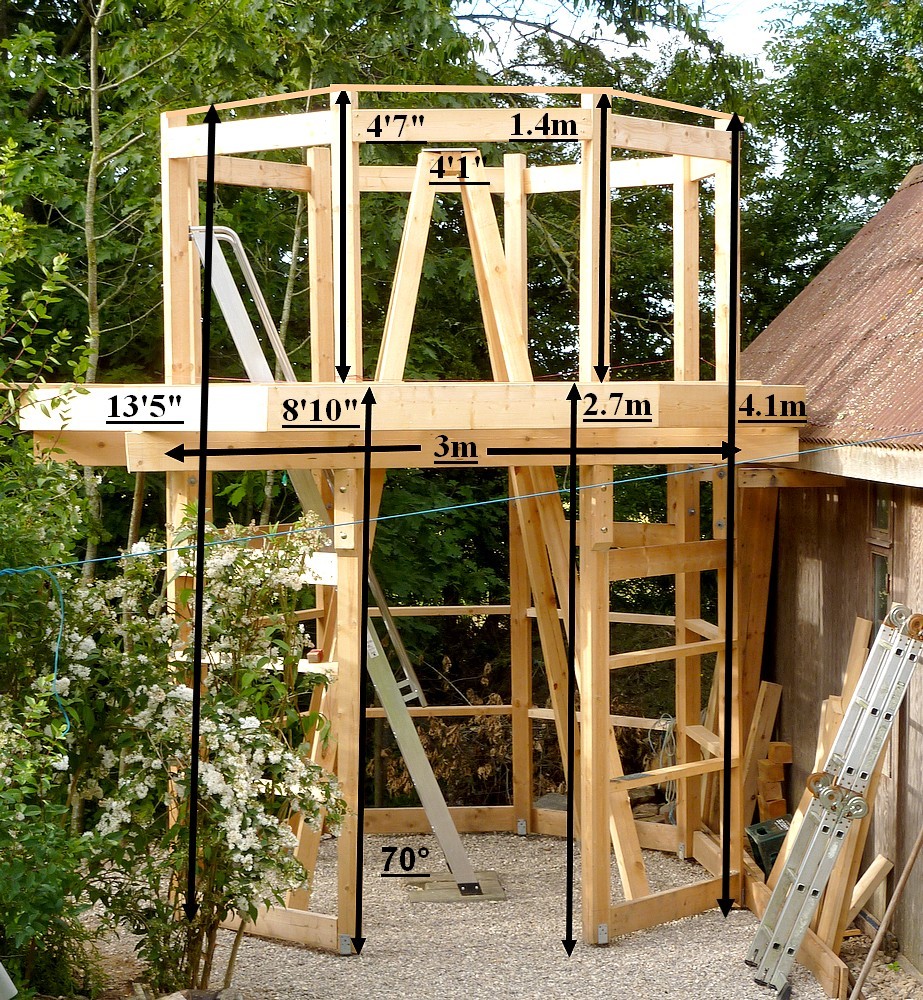
It is all too tempting to imagine the increase in diameter means the same increase in radius. By the time the mounting has been nudged towards the WSW the increase in radius is only about 2'. [60cm] 

I will, of course, gain from a much rounder building profile. With much slimmer arcs at the roller and dome, base ring level. The octagon is/was very wasteful of useful space. The heavy timbers even more so. Straight lines cut across valuable elbow room. Making binoviewing and solar wedges too selective. In when and where they can be comfortably used.  Or not at all! 

It all feels rather unreal at the moment. I am not used to having to wait [so long] for delivery. This is the age of instant gratification after all. Place an order and some online dealers will ensure next day delivery. The donor, calf dome "kit" may still be a full month away for all I know. Without any idea of its physical progress. Until I receive an email notifying me of impending delivery. 

It all depends on the dome being available and safely assembled within the garden. Without it, there is quite literally no new project. Meanwhile I can only imagine the sheer size and weight of the segments. 

Though I should probably be grateful. For having so much time to polish my pipe-dream rehearsals. Without the physical presence I am rather stuck on exact dimensions. I dare not forge ahead for fear of a complete mismatch and the wasting of some very expensive materials. Birch plywood does not grow on trees! 😉

The workflow should go far more quickly and smoothly than the last one. Where I was literally making that up as I went along. With the expert aid of others far more practised in building work [on the astro forums.] The dome and building became an exercise in compound mitres and precision cutting on machines I had never even owned before. Now their considerable cost can be shared with another project. I just wish I had owned these machines and tools years ago. 

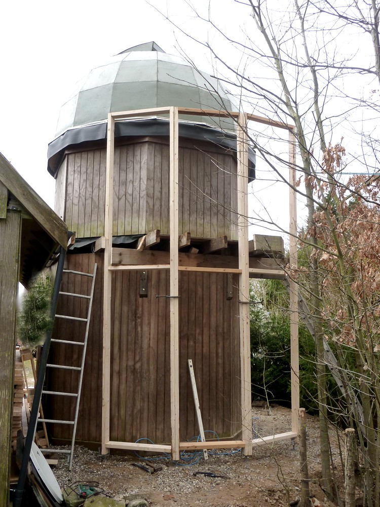
The most vital aspect, of the new dome, is its [hopefully] guaranteed weatherproofing. The observatory contents is not designed to be waterproof. The GRP dome should overcome the leaky handicaps of the plywood structure. I can make it much more windproof too. Without the problems of the rubber skirt lifting and slapping. 

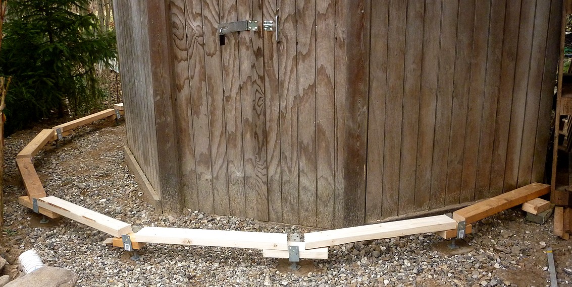
The new dome is round at the base. So a round, top ring on the building should provide a much more reasonable seal. I plan to raise the base ring up inside the dome slightly to ensure run-off does just that. 

The new building perimeter will no longer have exposed gaps between the joists. It seemed like a good idea at the time. To ensure reduced heat build up by providing lots of sub floor ventilation for a "chimney" effect. It didn't do much and even opening the downstairs doors had no obvious effect on the temperature differential. I constantly measured the air temperature in the deep, northern shade under the veranda. Then compared it, on the same in/out digital thermometer, with the dome's internal, air temperature in the shade. 

I'd also use my laser guided, remote sensing thermometer. To monitor the dome's plywood, panel temperatures. It was obvious that the panels perpendicular to the sun rocketed. While all others would read much lower. It should be remembered that the dome was constantly rotated to follow the sun. So the same panels became hot. The shutters provided shade to two vertical rows of panels.  So those just outboard of the open shutters were always hottest. As were the highest panels in high summer. When solar altitude was at a maximum. About 56° locally.

I tried suspending shade net above and below the light path across the open slit. To little, or no, obvious effect. Though it did help to reduce wind blowing into the dome. 

Only a highly reflective surface facing the sun would really help to lower thermal differentials. Something like space blanket would probably work best. Though I discovered that white, lightweight, woven "tarpaulin" was thermally neutral. I never got as far as cladding the shutters with this stuff. 

The dome manufacturers claim low thermal absorption on the outer coating. To protect the [more usual] animal occupants from heat stress in southern European, heat waves. Only time will tell if this valuable advantage is true. A near invisible, green dome, which also reflects solar heat, is an unlikely bonus in terms of domestic bliss! 

My incredibly tolerant wife was never keen on a white dome in Her garden. Much as I'd like to think the white would be thermally "superior." There didn't seem much point in pushing for a highly visible "carbuncle." What passes unnoticed from the distant road is inevitably more secure.  

*

12.2.21

12.02.2021 Cross-axis PA mockup.

 *

 Friday 12th -14C/6F at 9am this morning! Bright sunshine all day but remaining well under freezing.

I used a 4m long, telescopic pole to mock up potential Polar Axes for the planned Cross-axis mounting. It was a surprise to discover how long the PA needed to be: 3.6m! Just to allow the present Dec/PA axis crossing height.  The lower end of the PA would almost reach the present southern edge of the obs. floor! Raising the southern bearing on a support structure would shorten the PA and help to provide a clear pathway around it.

The North bearing would be 1.5m above the present roller support ring. With the Dec axis at the half way point at 2.3m. This is with a Cross-Axis PA centred on the present, GEM PA but extended, in direct line, [i.e. on axis] above and below it. These dimensions apply to the present, smaller, 3m dome. 

The larger 4.3m Ø dome would allow greater lengths and heights. If the axis crossing point is moved up the PA the OTAs need more room in the north side of the dome. Potentially making visual use more difficult due to head clearance problems. The higher the OTAs are mounted on the PA the less room there is for longer dewshields high in the southern half of the dome. Though the 4.3m done should be more than adequate for this. While the present 3m offers anything but adequate clearance for the big refractor's huge dewshield. 10" diameter x 18" long. Nor does it provide headroom enough in the north at low pointing altitudes.

I have ordered six more dome support & rotation rollers/wheels to match the eight originals. 160mm Ø in white Nylon, needle roller bearings. Each wheel with an individual 360kg load capacity. It seemed wise to have a roller above each new upright post to support the larger dome. 

It is difficult to judge how much friction is gained or lost with more or less rollers. The present dome has friction issues with the stiff, plastic stand up collar rubbing against the rubber skirt. I'll be glad to see the back of both. The rubber skirt is horribly noisy as it flaps [slaps] almost constantly in the wind. I hope to have much better sealing against the wind with the new dome.

Likely total weight of the new, fibreglass dome will be about 400kg. This is allowing for the shutters, laminated plywood ribs and much thicker, laminated, base ring. The weight of all that birch ply soon climbs once the laminations are added. Whole sheets of ply, in the form of cut arcs, simply vanish into the woodwork. 

I cannot remember if I ever worked out the weight of the present, wood and plywood dome. A lot of wood went into its frame. I remember it suddenly being much harder to turn once the 4mm cladding went on. Soon solved with the cranked, friction roller drive. Though I wouldn't want to be without it. Pushing the dome around manually is very hard work!

I cleared the 4" of snow off the observatory veranda in the afternoon. I keep wondering if I need one on the bigger building. It was handy to have a veranda when building and maintaining the smaller dome. Hopefully the new one wont need any more work once it is up there. I can access the top of the dome via the slit using inside ladders. Only the top, shutter, drawer slides will need occasional checking. 

That said, a veranda can add to the architectural interest of the building. Otherwise it might look rather austere or even boring. I would probably have to make wooden brackets to support the veranda on the new building. 

If I don't have a veranda I would need to fit secure tie off points for ladders. The dome could be rotated to bring the shutters to the front [south.] For easiest access to the lower, shutter, drawer slides.


*

11.2.21

11.02.2021 Post rearrangement.

 *

Thursday 11th 25F, another inch of overnight snow. With continuing frosts and possible snow in the forecast for the rest of the month. The ground will remain rock hard. Denying me the ability to continue with the foundation blocks.

After I had cleared away the snow I attended to the upright posts. They are now much more upright than yesterday. Which gives a better idea of the increased space available to the west and SW. 

The veranda facia boards will not be there in the future. Meaning the posts will have to connect to the nearest joists instead of being fixed to the veranda. So the mock-up is merely a geometric representation of the larger footprint.

I am waiting for the arrival and assembly of the dome to get some accurate figures for its internal diameter. Until I have the correct dimensions I cannot cut the roller support ring to size. Which would have allowed me to fix the full height posts. Even if I didn't have the rear, foundation blocks sunk into place. 

The building has to fit under the dome, with clearance, to stop the rain running straight inside the walls. I have used 2m as the radius for the foundation blocks. There should be 30cm difference in diameter. Though the dome must have some thickness at the base. The building's top ring can be adjusted to suit the dome's internal diameter and clearance needs.

It's all getting a bit Catch 22 at the moment. At least I am getting a rest from all the digging! Though repeated snow clearing and playing with the posts and ladders is giving me plenty of exercise.


*

10.2.21

10.02.2021 New boundary post mock-up.

 *

 Wednesday 10th. 27F. Snow still here but the wind has finally dropped. I was quite comfortable working outside in a fleece jacket.

I decided to do a mock-up with 2x4s [Metric 50x100mm] of the upright posts of the larger building footprint. There was a lot of packing and clamping involved while balancing ladders on the edge of the gravel pad. Until all the posts were more, or less, upright. Each post is resting on the metalwork jutting from its foundation block. Not an easy thing to photograph and still get all the posts into the picture.

Some of the posts would pass right though the present veranda. Requiring shorter posts to fit underneath just for this mock-up. I had no desire to start searching for the veranda fixing screws just to remove the necessary boards. Not under the hard frozen snow!

In the real construction the posts would reach right up to the roller supporting, building's, top ring. The mock-up posts were just what I had available from the intended, dome transport trolley. I'd need 4.2m posts for the real thing.

There are a lot of joists under the veranda. Making any likely ladder repositioning a bit of a chainsaw massacre. I'll look at that issue again when the new building is properly outlined.

Seeing the posts in place suggested a change in earlier panel building decisions. Now I am thinking 2x4 main posts arranged 'flat' [tangential] to the circumference of the new building. 

The plywood cladding panels could be edged with regulation [metric] roofing battens. [Probably 38x57mm] For lighter handling [than the full 2x4s] but still of very adequate strength. Two x 57mm almost matches the width of 50x100mm [2x4] posts for the panels to fit neatly together edge to edge. These panel edge battens would increase the [100x] 50mm deep posts to 87mm in depth.

If I wanted much more strength I could screw a 2x4 to the back of the first set of 2x4 posts. Either laid flat for 100mm overall + panel edge battens. [138mm depth.] Or, set on edge for a 100x150mm 'T' profile. [188mm total depth] 

The latter arrangement would provide greater beam depth for improved structural stiffness. [Due to the increased moment.] I have not bevelled the panel, edge battens in the drawing. [Above right.] I think I prefer the upper arrangement in the image [above right] as being more than adequate.

The interior angles of a multi-sided polygons become relaxed when there are so many sides. I am assuming 15 sides. 12 new + 2 existing but with the latter at wider spacing. So I added a fictional one. 

So: [n-2] x 180/n = [13x180]/15 = 156°. Using 14 sides in the formula results in 154°. An almost trivial difference.


The 100mm faces of the posts would be bevelled to half width. The joining faces of the panel, edge battens, also bevelled on the table saw.

I would add diagonal 2x4 braces internally between the upright posts. For a very sturdy perimeter structure. This would require compound mitres. Appropriately spaced, horizontal braces, of 2x4, could provide shelves. Or provide solid support for deeper shelves.


 *


9.2.21

9.02.2021 Stairway to the heavens?

 *

 Tuesday 9th -3C cold and very windy. A little sunshine around lunch time.

I was doodling the present, observatory stairs [stepladder] in my mind. When it occurred to me that I [presently] ascend to arrive at the trapdoor. With the outer observatory wall just beyond it. The handrails are literally resting against the low, veranda doors. The image shows an early set-up without the veranda doors or trapdoor.

The trapdoor cannot be lowered until I have completed the climb to gain the observatory floor. Then, unless these doors are wide open, there is still nowhere to go except sideways and backwards. 

I must step backwards to clear the fixed handrails which are welded to the big stepladder. Or, I must stop climbing at the penultimate step. Then step upwards and sideways onto the observatory floor. Which always seems like a physically higher step than between the rest of the stepladder treads. Even though it isn't. It is always an awkward movement. Made worse by the presence of the handrails or when carrying anything.

The image [left] shows the severe limitations in placing the stepladder within the octagon. The big stepladder rises inside the pyramidal pier. Then stops dead against the observatory wall. 

The upper pier cladding had to be cut out like a dog kennel. Just to allow my head to pass unhindered. This followed several, painful collisions! Only much later did I add the present [counterbalanced] trapdoor. Which itself had to be provided with pivoted toggles on which to rest when closed.

Now we move on to the much larger footprint of the expanded building.What if I could twist the whole stepladder in a clockwise direction? Bringing it much nearer to a tangent to the new building's [far more] circular footprint. This would require a new and larger rectangular clearance hole [presently 60cm x 130cm] in the observatory floor. Though now much further away from the mounting, the telescopes and the usual foot traffic area. 

The important detail is that I could continue to climb to the top tread of the existing stepladder. Then simply step straight through the handrails. Onto the observatory floor at exactly the same level. 

The stepladder handrails would provide some limited protection from falling into the large hole in the floor. Though there is now, no longer any need to access the ladder from the side and above. A suitable handrail and three posts can easily and safely protect the entire hole in the floor. 

There would probably need to be some trimming of existing joists. Which must then be boxed around the new hole in the floor with sturdy material. The missing strength must be carried around the hole and continue beyond. Just as it would be in a loft access, trapdoor situation, indoors.

Descent to the ground floor would mean passing backwards between the handrails. The 65° angle of the stairs and narrow [10cm/4"] treads do not lend themselves to forward facing descent. Not unless I replace the aluminium stepladder with a home-built, wooden and/or plywood version. One with a much more relaxed angle [55°?] and deeper treads. The problem then is how much linear space it uses up. 

Such a wooden replacement could be given a gentle bend in the middle. To allow it to follow the lower building's walls more closely and without requiring a curved stair or landing. Nor tapered treads. It could then arrive on the observatory floor parallel to the nearest observatory wall. Providing minimum intrusion into the obs. floor space. While allowing easier access from above and below. A newel post and handrail would provide protection to the hole in the floor. There being no need to add safety overhang as occurs with the metal, stepladder handrails.

*

8.2.21

8.02.2021 Early musings on cross-axis mounting support.

 *

English, Cross-axis mounting:

North or south mounted RA drive on the [planned] cross-axis mount?  A wireless mouse and keyboard require no close proximity for an imaging desk. Though they still have a minimum footprint. The high res. monitor still needs an HDMI cable to the laptop and adequate support. It all has to be carefully considered.

The rough drawing [Right] shows potential cross axis mounting support seen form the west. Two A-frames of 4"x4" timbers are raised at north and south. Inside the building but isolated from it. The A-frames provide the lateral rigidity for the Polar Axis. Though some lateral adjustment will be needed for polar alignment.

I imagined a [very stiff] curved plywood [laminated] bearing support above but well attached to the northern A-frame. The curved plywood structure would provide maximum telescope clearance while following the curve of the dome. The height and spread of the northern A-frame can be chosen to match the needs of the curved "extension." Probably reaching obs. wall height before the plywood takes over.

N-S stiffness can only be provided at the lower, southern end of the very long, Polar Axis. Where all the mounting and telescope loads must be safely resisted without causing a major obstruction downstairs on the ground floor. Nor by directly connecting it to the building. 

The fact that the observatory is raised demands serious attention to the support geometry. I have no plans to build anything in concrete, brick or blocks. Preferring timber and triangulation. Even plywood cladding where it makes most sense.  

Options exist for below-floor bracing. Where they won't inhibit free movement upstairs on the observatory floor. The lower [South] PA bearing can be placed at many different heights. Raised well above the obs. floor or placed low down. Even underfloor. Though the stepladder/stairs may well dictate certain arrangements are better than others. Each choice affects the geometry of the support system under the fixed 55° PA angle. The PA can be any suitable length but, again, will affect the support geometry.

The next drawing [left] has to be imagined in 3D. It shows the same arrangement as the drawing above but seen at 90° to the first. The two A-frames are upright in a N-S sense. The northerly A-frame much taller than the southern. I should really have drawn the northly one much taller.

Bracing from lower down to higher up on the A-frames automatically provides triangulation in several planes. A horizontal cross beam, [or beams] just under the obs. floor, would enjoy the same gain in stiffness by triangulation from rising braces. [Shown, at left, in red.]

I'm hoping the increased and much rounder 4.3m footprint will feel more like a cavern in the dome and downstairs. At least in comparison with the present 3m octagon based observatory. With its very wide, [2x10] timber, top ring reducing the usable floor space even further. The [present] huge, pyramidal, central pier also sets limits on the ground and obs. floor arrangements. 

A cross-axis is much more bulky than a GEM on a central pier but we shall see. I have no intention of building a cross axis without doing extensive "homework" first! Which usually just means daydreaming in my case. New ideas just pop into my head if I ignore the problem and let it rattle around for a while. I can easily make mock-ups using battens. To get a feel for dimensions, bulk and telescope sweep. I plan to do so on the ground using the arc templates to indicate the dome curvature. Just to get a feel for a suitable length for the PA.


*


7.2.21

7.02.2021 Onwards and upwards? Postscript.

 *

Postscript: I have just been over to the observatory in the freezing gale. Where I lifted the big stepladder onto 2"x4" packing pieces on the ground floor. This effortlessly achieved a more comfortable 65° lean. I don't think 60° is nearly so easily managed. Even at 65° the treads were visibly tipped downwards. Better though than tilted backwards! 

A 50mm/2" rise in ground floor height is no problem at all. I had deliberately buried the paving slabs into the gravel. To obtain the supposedly optimum, 70° angle. This was to achieve perfectly flat treads. Which I saw as necessary at the time.

Once the larger building footprint is completed I will be able to move the stepladder well forwards. To lean against the new boundary. Providing greatly increased clearance at Obs. floor level. Only then will I be able to better judge the position and best orientation of the ladder. 

I might even be able to swing the entire ladder at an angle to the floor joists. Particularly if I can get rid of the huge, pyramidal pier. To make way for a cross-axis mounting.  Which will use upright [but leaning together] posts. Rather than forming the doubly inwardly sloping edges of a four sided pyramid. 

I may prefer to have the ladder rising through the floor in another place. Having the ladder [presently] leaning towards the west is actually the worst possible orientation for my normal use! Morning, solar imaging, or visual observation, automatically places the camera/eyepiece/focusers and etalon out over the ladder and the void. Forcing closure of the trapdoor. 

South is also poor because I usually want to park the dome shutters facing south. Because I need clear access for those. I most often need to look out to the south too. Towards the house and drive. I sit with my back against the north side at the moment. With my computer imaging desk wrapped around the pier on the north and east side. I use a wireless keyboard and mouse. With the laptop closed and the internet running on wireless from indoors. I believe my AOC hi-res monitor has wireless compatibility but it will still need its PS cable.

I want to avoid direct sunshine falling on myself. Presently my large GEM offers lots of shade. The monitor is best facing north. To avoid sky reflections when the shutters are open. A more compact but [castor] mobile desk may end up as the best compromise. With the drive cables to the laptop and REW boxes setting the limits on where these can be sited relative to the mounting.


*

6.2.21

6.02.2021 Onwards and upwards?

 * 

Saturday 6th 21F/-6C cleared to a lovely sunny day. Except for the easterly gales! NO imaging today!

I swept up the snowdrift from the obs. floor with a dustpan and brush. Two dustpan loads. It was 25F/-4C in there and draughty.

Sunday 7th 24F/-5C. Continuing cold with gales but now overcast. With a snow drift warning. No building progress today.

I had the idea of reinforcing the new building using diagonal, timber braces alongside the access stepladder. These would be bolted to the obs. floor joists and descend to buried, concrete, foundation blocks. The braces would ensure the whole building would have to lift in a westerly hurricane rather than just falling over.

I am also looking into a gentle spiral staircase. To ease the climb while carrying "stuff." The near 70° stepladder is far too steep to provide handsfree climbing or descent. I have been up and down the stepladder countless hundreds of times by now and would much prefer something less steep. Somewhat surprisingly some stockists claim that the stepladder can be lowered to a 60° angle. The problem then is that the treads would no longer be horizontal. [See Postscript below.]

The increased radius [2m] of the new outer wall would provide more room for a 1/4 turn stair up to the raised obs. floor level. The one major problem is that this would require cutting away a central floor joist. The new floor opening would need to be very strongly framed to regain the lost strength. Though this area is outside the existing veranda. Allowing greater flexibility in design.

Here, I am thinking of increasing old age and my knees becoming a problem on the present stepladder. It is also impossible to descend without going backwards. 

Our [cottage style] indoor stairs at 58° are at the absolute limit for face forwards descent. My Achilles tendons strike the treads at every step. After 25 years of constant practice it feels safe enough but the experience simply cannot be carried over to the observatory stepladder. 

The 10cm/4" deep stepladder treads are excellent for providing feedback for balance. There are 10 treads for a 2.7m [8'10"] rise. There is  a rise of 26cm vertically between the treads or 23cm clearance. This is without any overlap between the ribbed, aluminium profile treads. 

This thing is usually called a warehouse stepladder and I would not have been without it. Made by Jumbo. They make a whole range of ladders and stepladders. This sturdiest model has built in, tubular handrails.

The main problem is just that the user's centre of gravity falls outside the safe limit when both hands are not firmly on the handrails. 

The climb and descent with the heavy laptop case is often a daily chore. There isn't room to hold the weight ahead of me on the climb. This is because of the steepness of the ladder ahead of me. So the laptop case has to be carried hanging down behind me. Which throws my balance backwards. While the other hand is holding onto one of the handrails. Fine in warm weather but slippery gloves are no fun in winter. Even [supposed] industrial, dipped cloth, rubber faced gloves are often remarkably slippery on polished aluminium.

Thank goodness I did not settle for a normal ladder. It is almost certain I would have given up or even fallen off by now! Don't ever be tempted to save money on your only means of access if you have a raised observatory. 

I don't even recommend a hole in the floor without the safeguard of a safety handrail. I fitted a bright LED light under the pier. To throw light onto the ladder when the trapdoor is open. I was careful to have the top tread of the stepladder at obs. floor level. So I can use it as a stepping stone to cross the yawning drop.


*

3.2.21

3.02.2021 Poor seeing conditions! 😉

 *

Wednesday 3rd February. Snow is expected to continue all day. It amounted to about 125mm/ 5" on flat surfaces. Though with some drifting.

Thursday 4th and Friday 5th. The snow has blown through the floppy rubber skirt beneath the shutters onto the observatory floor. I had turned the shutters into the wind to avoid precisely this problem but to no avail. I really ought to have backed up the rubber skirt just there but hadn't. It was handy for looking out without having to open the shutters when it was wet or windy.

There is also a gap between the shutter ribs and the slit ribs when the shutters are closed. Which made me fear major spindrift incursion if the shutters had been sideways onto the wind. Not a major problem and I shall easily clear up the snow long before it melts. Another ten days of continuous frost are forecast. 

The wintry conditions have caused a major halt to burying foundation blocks for the larger observatory perimeter. I continue to rehearse all the required steps in my mind. Even spending some hours watching YT videos on the means to handling large and heavy loads while working alone. 

I still like my earlier plans for a very large trolley built from 2x4s. With the doubled, trailer pilot wheels, with jacks, to aid easy movement, rotation, levelling and lifting. Bridged ladders with my chain hoist, boat winch and pulley blocks will all provide backup when needed. For assembly of the segments and other tasks. Each segment weighs 160lbs. Which is not a suitable weight to be lifting at my age.


*


*

1.2.21

01.02.2021 Icy cold!

 *

Monday 1st February. 32F. Sunny periods after a cloudy start. Signs that small birds have been roosting in the observatory.

I completed the rear, worm bearing brace but now I am struggling with too much friction on slews. Which doesn't make sense because I have ready slacked off the bearing pre-load screws. 

Tuesday 2nd. 10.45  -8C, 17F, Mount and scopes frosted all over! Cables stiff. Trying to image but the objective is dewed up again. Dew heaters on. A blast from the hairdrier helped on the D-ERF.

RA drive stalling on slew but tracking well. I must attend to that. Removed the screws and bearing brace for only slight improvement. Telescopes seem well balanced.

Removed the D-ERF to warm the dewed objective. Held the D-ERF in front to avoid cooking anything with unfiltered heat. Internal dewing doesn't react to the hair drier. Dew heater has reached 75F. I really do need to make a seriously insulating muff for the front end. I am losing imaging time to dew.

11.40 31/29F I can see two small dark sunspots. Nearing western limb. 1/3rd solar disk from the pole.

12.05 33/30F. Dew spot inside objective finally shrinking.

12.50 35/30F Have been trying to capture the spots in H-a and white light without success. Seeing too soft and won't support Barlows. Cloud has intervened. It must be lunch time!

The afternoon was no better so I tidied up. Then turned the dome to face the shutters to the east. A week of snow is forecast with easterly gales at times. Which suggests spindrift inside the dome and drifting elsewhere. I have covered the telescopes with a huge poly bag to try to protect them as much as possible. 

I should have bought a dedicated [middle-weight] tarpaulin ages ago. The lightweight ones are garbage. The "proper" PVC tarpaulins are far too heavy and far too stiff to fold up [cold] when not in use. Trying to manage one from a stepladder after a frost is too ungainly. I have tried covering the telescopes with my 350g/m² car trailer tarpaulin.

There is a midway selection provided they are not subject to too much UV or flexing wind. Unlikely inside a dome. Unfortunately most tarpaulins are supplied in unhelpful sizes for horizontal telescope covers. It would probably mean cutting a standard one in half and fitting new eyelets. I have tried spring clamps for holding them in place but they are not ideal. Perhaps I should try a lightweight scooter or motorcycle cover? They sell for as little as £10 equivalent and are not all oddly shaped for raised handlebars. It is not as if it will be subject to normal outdoor weather stresses.


*