*
 It seems I don't have to go back to an old-fashioned and completely redundant secondary collimation system:
Tilting secondary holders can work against a compression spring. With two raised points to fix the desired hinge line. A compression screw on the third point of the triangle adjusts the secondary tilt. Thanks for the useful tip, Clive!


 One does not really want to use loose hand tools in the dark to adjust the telescope's collimation. So I shall fit a length of M4 rod with a small hand adjuster knob in place of the temporary screw shown here. This will all remain in the shadow of the secondary without contributing to diffraction effects.
 Some spider designs incorporate rubber or spring loading for the screws. This means the screws don't become loose but it doesn't alter the fact that the diagonal tilts along irrelevant hinge lines. I borrowed the single tilt design from Mr Royce's website. Though I clung onto my traditional, tubular mirror holder rather than gluing the secondary to a 45 degree plate. I just don't trust glue when the OTA has to be moved around every time I want to observe. Then bumped back into storage afterwards.
Note that no attempt has been made to make an "impressive" spider and secondary holder. This is just an exploratory design, using scrap materials, to prove its ability to render a well-functioning telescope. Improving the finish and appearance are just time wasted at this point. The design may as much a failure as the brass U-spring design. Though this one does seem far more promising than the last.
Under compression.
 It seems I don't have to go back to an old-fashioned and completely redundant secondary collimation system:
Tilting secondary holders can work against a compression spring. With two raised points to fix the desired hinge line. A compression screw on the third point of the triangle adjusts the secondary tilt. Thanks for the useful tip, Clive!

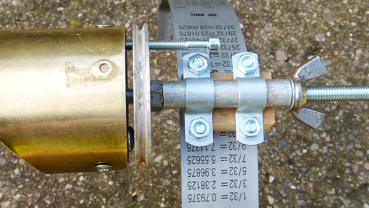
My first attempt with everything safely in compression. A spiral compression spring sits in an oversized hole inside the oak plug at the base of the brass mirror holder. I have also re-bored the hole in the plug slightly larger to allow the secondary holder to rock freely on the threaded rod. (studding)
The threaded rod has a Ny-loc lock nut at its tip to stop the spring from escaping. The nut will also remain safely in place when the wing nut is loosened to remove the diagonal mirror housing.

I have cut an M6 thread in the central hole in a scrap alloy pulley backed up with a locknut. This is just to ensure the pulley remains firmly fixed on the screwed rod and cannot tilt. The pulley is marginally larger than the mirror holder. Meaning that a clean diffraction disk is seen in the light path at the expense of a tiny increase in actual diameter. The fact that it was once a pulley is of no concern. It just saved me sawing out and turning a disk on the lathe. IT will be painted flat back later along with the rest of the spider assembly.
Two dome-headed wood screws (fixed into the wooden plug) rest against the pulley face under spring pressure. These screws act as the hinge line for secondary mirror tilt. Their size doesn't matter. I just used some screws which matched my immediate needs.
A long M4 socket head bolt in another threaded hole near the edge of the pulley pushes against the oak plug. Also against spring pressure. This is the tilt adjustment for optical collimation.
 One does not really want to use loose hand tools in the dark to adjust the telescope's collimation. So I shall fit a length of M4 rod with a small hand adjuster knob in place of the temporary screw shown here. This will all remain in the shadow of the secondary without contributing to diffraction effects.
I have now added some pictures of the secondary holder dismantled to show the actual construction.
It is all very simple and logical. The secondary mirror is now incredibly firm and stable and under the fine control of the tilt adjustment screw. Though only about 1/2" long (12mm) the compression spring is easily strong enough to avoid backlash during tilt adjustment. Provided the spider vane is reasonably aligned in the tube then the required mirror tilt should be minimal. In fact it should point straight down the tube but the tilt allows for any slight variations in spider alignment and mirror centration.
The traditional 3-screw adjustment of many secondary mirror spiders is quite unnecessary. In fact it usually causes great confusion because the secondary mirror tilts sideways as well as back and forth. The mirror actually tilts on 3 diagonals which have absolutely nothing to do with mirror alignment!
What is worse the mirror becomes floppy as one adjustment screw must be loosened to allow another to be tightened. So the hapless would-be collimator goes round and around and around adjusting screws in turn. Usually without succeeding in what should be quite a simple task.
 Some spider designs incorporate rubber or spring loading for the screws. This means the screws don't become loose but it doesn't alter the fact that the diagonal tilts along irrelevant hinge lines. I borrowed the single tilt design from Mr Royce's website. Though I clung onto my traditional, tubular mirror holder rather than gluing the secondary to a 45 degree plate. I just don't trust glue when the OTA has to be moved around every time I want to observe. Then bumped back into storage afterwards.
Note that no attempt has been made to make an "impressive" spider and secondary holder. This is just an exploratory design, using scrap materials, to prove its ability to render a well-functioning telescope. Improving the finish and appearance are just time wasted at this point. The design may as much a failure as the brass U-spring design. Though this one does seem far more promising than the last.
Here is a ink to Mr Royce's website page on his tilting, secondary mirror, spider design:
Click on any image for an enlargement.
*
No comments:
Post a Comment