***********
 An update: CSK screws fitted to the
shroud. By countersinking the threaded holes in the plastic, behind the
brass shroud, I was able to pull the screws in quite tightly. I may redo
the countersinking to sink the screws heads in further out of the light
path. I lost the soldered mirror retaining tab while truing up the old
shroud into a more perfect cylinder. It will have to be replaced.
An update: CSK screws fitted to the
shroud. By countersinking the threaded holes in the plastic, behind the
brass shroud, I was able to pull the screws in quite tightly. I may redo
the countersinking to sink the screws heads in further out of the light
path. I lost the soldered mirror retaining tab while truing up the old
shroud into a more perfect cylinder. It will have to be replaced. 
The holes were then drilled with a small drill and then opened out with a larger drill to size. This is much more accurate than trying to drill full size. There isn't usually enough room for the nose of a larger drill to start well in a centre punched hole. Boring the smaller hole first ensures that the larger drill runs true and accurately centred without wandering.
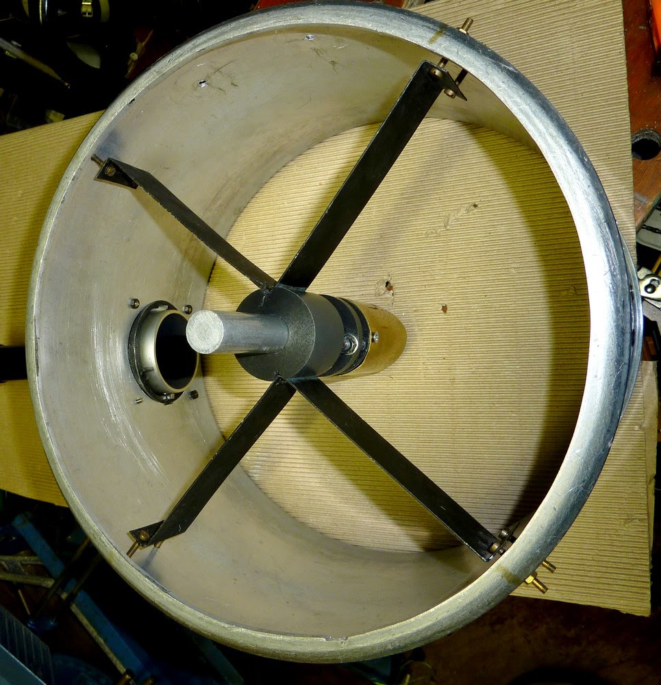
An
oblique view of the new secondary mirror support in place within the
cell. Even with the tension nuts only finger tight the stiffness at the
hub is absolutely amazing.
The flange formed by the bottom of the cooking pot is highly resistive to radial compression forces. Ensuring that the walls of the cylinder are not pulled in. Though it is probably unnecessary I may fit packing pieces under the vane legs to avoid shifting from shocks while rolling the OTA on its wheels across the garden to its mounting.
 Here I have fitted small pieces of beech packing under the feet of the spider vanes. The screws only just pinch the feet up against the packing pieces when tightened. The stiffness of the vanes themselves is thus maintained by the tension forces applied.
 The distance between the centre of the tube and the outer face of the focuser sets the range limits of the minor axis of the elliptical secondary mirror. This distance is 260mm according to the tape measure. [Or about 10.2"] According to online sources this sets the minimum secondary size as 1.3" for 0.25" diameter illuminated field. The maximum suggested is 1.69" for a 0.5" illuminated field. So I could reduce my secondary size [from the present slightly oversize 1.81" m.a.] for purely planetary and lunar work. Though I would then lose some off-axis illumination for low powers in 2" long focus eyepieces.
http://www.loptics.com/ATM/diagonals.html
 Alternatively, I could lower the focuser height by purchasing an upmarket, low profile focuser. Preferably one with slow motion focusing. A not inexpensive purchase for the optical return on the heavy investment. Or, I could reduce the diameter of the secondary cell. This automatically reduces the distance of the focal plane from the optical axis of the main tube.
 The effective secondary diameter [m.a.] is a moveable feast. To reduce the secondary size would involve a completely new secondary holder and spider. It would also involve the expense of a premium quality secondary to match my very high quality primary. The main advantage of an oversize secondary is that the edge of the secondary mirror is much less likely to be involved in high power image forming. The edge of the secondary is usually the weakest point optically because it may be turned down from heating effects during polishing. The glass expands and is then polished off. As the glass cools the edge shrinks below the rest of the optical surface.
As the magnifying power of the instrument increases, so the fully illuminated, field diameter at the focal plane shrinks. A smaller secondary makes most sense if one never uses low powers and demand the highest potential image quality. [If the seeing conditions allow it!] In the best seeing conditions the image will be free from the deleterious effects of diffraction from using an over-large central obstruction.
 Further progress this afternoon: I soldered a new secondary mirror retaining tab. Then replaced a plywood plate with a nice bit of Tufnol for much better stiffness in clamping the secondary cage. By leaning the OTA at 45 degrees against the workbench, re- collimation with the Cheshire eyepiece is now a piece of cake. All thanks to the new spider/secondary holder. When an adjustment is made it is absolutely positive and without any "spring." Adjusting the curved spider was just too vague for my liking. I'm hoping for the sky to clear but it is mostly overcast. Now I must fit sights and/or a finder. No shortage of finders but they have dovetail base fittings. I am still unsure whether I shouldn't have finders or sights half way up the spars for easy location from the ground.
In the end I found an incredibly simple way of adding two finders without modifying or even defacing the dovetail castings. The dovetail based, stand-off stalks are hollow castings. So I just drilled a 4mm hole in the middle of each dovetail and inserted a screw from inside the stalk itself. Both castings have a small tongue extension on the base at the closed end of the dovetail. For the larger 8x50 finder I filed a small slot in the cell for the tongue. For the smaller Vixen finder I just added a thin packing piece under the dovetail instead. Though I could just as easily have filed a slot in the cell for the small tongue and may do so anyway. After tightening a couple of nuts to lock the dovetail bases onto the cell the finders were perfectly solid. The finders have added some weight at the top of the OTA so the balance point will have moved upwards slightly. The weather was far too foul to put the OTA onto the mounting to check. When the weather is kinder I shall take some better pictures.
Click on any image for an enlargement.
************
No comments:
Post a Comment