*
Seeing the appearance of the side beams in practice helped me to decide if I really wanted to continue. The earlier supporting beams were certainly sleeker but seriously lacked torsional rigidity. The primary cell would sag around the beams with changing attitude of the OTA on the equatorial mounting. This was disastrous because it meant constantly having to re-collimate the optics every time I moved to another object to observe. Adding side beams would have helped but looked just too damned ugly! The lower paired beams should have been reduced to only one lying flat. With another mounted on top to make a four beam arrangement.

The secondary cage has been turned by 45 degrees here to bring the focuser to a comfortable angle for altazimuth use. The finder mounting bracket is now on top of the OTA for right eye viewing. Though it is easily moved to a new site simply by drilling a single hole for the mounting screw. The upright focuser was fine on the OTA when equatorially mounted. But would be difficult to reach with the OTA altazimuth mounted on Dobsonian bearings.
If a smaller section, rectangular alloy tube were readily available I could add them to the tops and bottoms of the OTA for altazimuth use. Builder's spirit levels use such sections but I have not yet seen these available as "bare" rectangular tubing. Certainly not in readily affordable 2m lengths in DIY outlets. The bending loads on an altazimuth OTA are very different from one which is equatorially mounted. With an altazimuth the bending forces are mostly in the vertical plane except when the tube is being lightly pushed in azimuth.
 The
rectangular, alloy, side beams provide excellent vertical support due to their
considerable depth. When the beams are placed "flat" that depth is
absent and the beam is not remotely as stiff in that orientation. Thus
it would make little sense to add these much larger beams at the top and
bottom of the OTA for altazimuth use. The greater dimension of the
beams would become complete overkill in the horizontal plane and add
little more than unnecessary mass.
The
rectangular, alloy, side beams provide excellent vertical support due to their
considerable depth. When the beams are placed "flat" that depth is
absent and the beam is not remotely as stiff in that orientation. Thus
it would make little sense to add these much larger beams at the top and
bottom of the OTA for altazimuth use. The greater dimension of the
beams would become complete overkill in the horizontal plane and add
little more than unnecessary mass.Though the main beam's wide spacing does already add considerable lateral stiffness. Which will depend on firmness of attachment to the cells. Adding two more [large] beams top and bottom would make excellent sense for an equatorially mounted OTA. Which subjects all of the beams to every possible orientation in use.
 In
the end I have decided to use more [heavy] channel section to make some really strong
beam-spacers for the primary cell. Narrowing the 2" high channel webs by
1/2" made the side beams parallel despite the alloy secondary cage being
slightly larger than the primary cell. As was the plywood rings and 30cm cardboard tube secondary cage. I am still not completely sure that simple compression, with through, clamping screws, will hold the pot firmly to the channel and beams. I was considering adding rubber hose, slit along its length, to the long edges of the webs for more friction and to reduce cosmetic damage to the primary "pot."
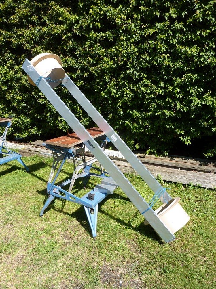
In
the end I have decided to use more [heavy] channel section to make some really strong
beam-spacers for the primary cell. Narrowing the 2" high channel webs by
1/2" made the side beams parallel despite the alloy secondary cage being
slightly larger than the primary cell. As was the plywood rings and 30cm cardboard tube secondary cage. I am still not completely sure that simple compression, with through, clamping screws, will hold the pot firmly to the channel and beams. I was considering adding rubber hose, slit along its length, to the long edges of the webs for more friction and to reduce cosmetic damage to the primary "pot."These images show further mock ups with the side beams and channel spacers still hanging from cord. When finished, this beam arrangement should provide serious stability and lack of flexure in the primary cell without needing the former [and much heavier] support beam system down below.
The Dobsonian altitude bearings can be attached to the side beams via a sliding clamp system to allow for easy, coarse balancing of the OTA.
These 5" long x 4" alloy channels @ 1lb each weigh no more than the 4" x 1" timber which I first considered for beam spacers. I might well invest in a decent quality, 3/4" metal hole saw to reduce the mass of these channel sections even more.
 With the compression loads applied over such a large area the
beams should remain firmly attached to the alloy pots without twisting.
Internal reinforcing strips will support the clamping screws where they
press on the primary cell just as they did before with the spar or "under-beam" system.
With the compression loads applied over such a large area the
beams should remain firmly attached to the alloy pots without twisting.
Internal reinforcing strips will support the clamping screws where they
press on the primary cell just as they did before with the spar or "under-beam" system.Removing the lower spars produced a minimalist but rather odd looking OTA. Because it looked too wide the great length seemed to have shrunk.
The introduction of multiple baffles between the beams would help to improve OTA stiffness locally at the cost of increased weight. Unless these baffles were joined together by stringers there would probably only be local resistance to lateral, beam bending.
I am keeping an open mind about using the plywood rings and cardboard tube secondary cage in preference to the existing alloy pot. They are both the same width between the beams in practice. So require no beam modification for a straight swap later on to save a little weight.
Click on any image for an enlargement.
*
No comments:
Post a Comment