31.12.20

31.12.2020 Reinventing the lever.

 *

Thursday 31st Dec. 39F and overcast again.

My back continues to trouble me after the last bouts of weight lifting idiocy. I am facing some seriously heavy hurdles on the way to to success on the new building project. 

So I was thinking about ways to overcome my age and new-found fragility. The huge weights I have been lifting and moving are completely beyond the red line for young, manual workers! I am 73 and the heavy lifting must stop before I seriously injure myself.

I have several, sturdy, folding, builder's stepladders. One of these [image right] could be abused to act as a fulcrum for lifting the heavy, concrete, foundation blocks. [12 x 35kg or 70lbs] 

All it needs is a series of ropes tied between opposing rungs of the symmetrical stepladder. A length of 2x4 can then be used as simple lever to move the blocks individually. From their storage pallet and over to their carefully placed excavation. Probably in steps or stages. With the ladder following behind.

The massive weight of each block seriously hindered lowering them correctly into their holes last time around. That was when I was still only 70. Leading to gravel being pushed back into the carefully excavated holes. Which meant more heavy lifting and further excavation before positioning again. All very inefficient!

The multiple rope loops will allow freedom to adjust the degree of movement and the vertical lift and lower required. A smaller timber section would arguably be adequate to the task as a lever. Though a 2x4 has enough extra weight, on the long side of the simple lever, to aid the lift. Thereby reducing the effort required.

I have already mentioned using doubled, 4m lengths of 2x4s for the building's upright posts. To avoid handling such long 4x4s. Which are simply far too heavy for comfort to stand up on end by physical effort alone. These vital posts will support the dome's base ring rollers and define the outer structure. 

A rope pulley could be hung from the veranda to aid getting the 2x4s quickly upright. I don't think a boat winch is really necessary. A 2x4, jutting from the dome observation slit, could be rotated with the dome. To provide flexibility in the position of the lifting pulley. This would provide more height and act as a crane jib.

A thinner, plywood, ring template will be far easier to handle than the heavy 2x18mm thick rings which I constructed last time. More laminations, of thinner plywood, could provide many more, staggered joints and higher strength overall. The sheer weight of the last ring made it impossible to remain flat under its own stiffness. Requiring crossed timbers for support each time it was lifted.

I used large sections of solid timber, 2x10, last time for the roller support ring. Which, though strong, were overkill and subject to twisting as they dried out over time. A plywood top ring can be reinforced with a lighter, timber ring. Clamped, glued and screwed underneath it. This will also help to tie in the upright posts far more effectively. Rather than using long, toe-nailed, vertical screws, sunk into the end grain of the upright posts.

I am still considering safe ways to lift the three, large and heavy, dome sections. This will be required to initially fit the dome together. Once this is achieved I can more easily lift and move the dome as a unit. The centre top is reinforced for repeated lifting by tractors with front lifts via a provided ring. I can take advantage of that strength for internal lifting in small stages. Once I have the dome on its full trolley I should be able to move it about on the doubled, trailer jockey wheels.

*

27.12.20

27.12.2020 Broadhust Clarkson & Fuller website.

 *

While I was browsing I found this website and an old video from the Broadhurst Clarkson and Fuller workshops in London. 

Broadhurst Clarkson and Fuller Ltd - Broadhurst Clarkson and Fuller Ltd

https://youtu.be/46O1ogG0AiA 


*

27.12.2020 New veranda options or a balcony?

 *

I will lose the existing veranda as the new building's footprint expands to [partially] enclose it. Mostly to the W, SW and south. Less to the north and nothing to the east. Where there is no veranda next to the shed roof.

Now I am wondering if I could use the largest "shelf brackets" to be found in the builder's merchants to remake a new veranda. The old veranda added a distinct touch of style. Enhancing the otherwise plain, "oversized pencil-shaped" tower. The veranda also provided safe and easy access to the exterior of the present, plywood dome for maintenance and sightseeing. The existing veranda was made of mitred, larch, terrace planks over softwood joists. The planks being arranged parallel to each side of the octagon.

The "industrial sized" shelf brackets are rather limited in size. 300x550mm is the largest I have found online so far. 550x550 would be much safer and far more useful. I bought several examples for my workshop for making lumber shelves. I'd rather not measure them today. Because of the driving rain and fierce gales. 

Failing that I'd just have to make my own, wooden, diagonal brace "shelf " brackets. Like the working platforms on antique, wooden windmills. The main problem there is that rain would probably run down the sloping braces and into the building. Though lead or DPC could be sandwiched between the wooden brackets and the building's plywood walls.

Straight lengths of steel/iron plumbing pipes could be employed to support flying joists. This would require large holes be drilled in the existing floor joists. This would only work with the drill perpendicular to the existing joists.

Various joints, flanges and straight, plumbing sections can be used to make supporting brackets. That would avoid rain running into the building. 

A simpler, front balcony? That would allow work on the lower dome. Which can be rotated to bring the relevant section within reach. I don't really fancy putting up a tall ladder against the building. To do work on the dome up so high. Not without some extra security. There would be literally nothing to which to attach a safety line unless I added large, eye-bolts. Only narrow sections of the dome exterior can be accessed through the open, observation slit from tall stepladders inside the dome. This access is shutter dependent.

An alternative would be stairs up to a protected landing at observatory floor level. Reduced exterior security and exposure to winter weather causes me resist this option. I would also have to duck under the building's top ring to gain access to the dome. 

So it is a toss up between my being able to bend sufficiently in increasing old age. Or being able to climb the steep inside steps at 70°. A larger building does offer slightly more room inside for a slightly more relaxed angle of stairs. I could rout out some wooden steps. 

Tangential stairs are another option. Though with the same "ducking and diving" problem if they were exterior. A gently spiralling interior staircase would be feasible but at the mercy of obs. floor joists . This would still leave a large hole in the dome level floor. Requiring a handrail and trapdoor at observatory level for safety. 

The least difficult option is to move the present warehouse ladder nearer the western wall. With the pier moving in much the same direction there would be little useful gain in headroom. I would still have to climb the steps inside the pier to gain access to the new dome. There would be a slight complication if I rotated the entire, pyramidal pier slightly to align it better to true north. It is presently oriented more like NNE/SSW. 

Which only produces some very minor clearance issues when the telescopes are vertical. The pier being only slowly tapered from its huge footprint at ground level it remains large even at the top. Being a plywood clad pyramidal frame, this does not offer much of an obstruction on the ground floor. I simply left the four 4x4s bare below the observatory floor level. The timber legs are bolted firmly to the steelwork brackets attached equally firmly to their four, concrete foundation blocks.  

There are other issues with joists and flooring at observatory level. I cannot simply remove the octagon's upright posts willy-nilly. The new uprights are almost a meter further out in the west. Which might require extensions to existing joists to carry some of the enlarged floor loads. I'm hoping the new uprights will be close enough to the present floor joists not to be a real nuisance. 

Some trimming of the veranda flooring is likely though for the new uprights. The observatory's larch flooring is parallel with the octagon's north and south sides. Albeit out of line with true north. My plan to rotate the larger building's footprint around the fixed easterly upright posts helps the northerly orientation slightly. The pier's 4x4s pierce the obs. flooring with deliberate mechanical clearance. 

So yet another issue to attend to. I'll be lucky of there is enough usable larch flooring to make good inside the enlarged dome. The original timber stockist of the larch flooring has long retired and closed up shop. I rather like the untreated planks for their traditional look. Though they were rather costly at the time. 


*


26.12.20

26.12.2020 45mph gales tomorrow. More dome musings.

 *

Saturday 26th. Another grey day with rain. 45mph gales forecast for tomorrow Sunday 27th. So I have lashed the dome down to the massive pier with ratchet straps. Several hundred kilograms of reserve loading will be added to the eight, dome restraining disks which constantly overlap the base ring.

I have been looking back over my last dome build and the extraordinary way I went about it. Nothing was really planned and it simply evolved as I went along. An interesting fact which I rediscovered was the weight of the bare wood and plywood dome. 

The bare shell, without the hefty base ring and shutters, weighed about 300 lbs. So one can estimate that it weighs as much as the much larger [but still bare] fibreglass dome. The shutters and base ring, of that too, will add to the overall weight. I can still remember how covering the dome with 4mm ply added to the difficulty of rotating the dome. Which quickly led to my adding the friction roller drive.

I hope the new dome will have been much better thought out than the last. Reducing the modification time to perhaps, only a few months. I plan everything in my head and write it down here. Almost as I go along. This way I can fix details for onward consideration until that stage draws closer. Thereby avoiding the making of costly or time wasting mistakes. New ideas constantly pop into my head.

The entire building must be enlarged before the dome can be lifted into place. Though the original building now offers stability and a safe working platform which was completely lacking when the first was built. It would be ideal if I can get the larger top ring safely fixed up there. To guide the position of the new, upright posts. In comparison, the last build was more like constructing a castle in the air while working at arm's length from the ground. Which was hugely wasteful of time as I constantly erected and moved my few ladders.

Being able to raise the larger building around the first is a huge advantage. I can add support struts for the building's top ring wherever they are deemed necessary. Which will give me an accurate guide for spacing and fixing the new, upright posts. Further layers of plywood ring can be laid on top of the first for increased strength and stiffness. The last building used heavy, 2x8s laid flat with mitre joints between them. 

As mentioned before, I plan to use 2x4s fixed side by side this time. Instead of the massively heavy 4x4s x 4 meters of the last build. Which were rather prone to twisting and cracking as they dried. I may even add diagonal 2x4 struts to help spread the loads more evenly into the smaller panels. 

The cladding of decoratively grooved 12mm plywood adds a strengthening and stiffening, stressed skin effect. Which could be considerably increased by lining the new building with matching 9mm ply. Some of the original plywood panels could be cut down to clad the larger building.


*

25.12.20

25.12.2020 Three spots.

 *

Friday 25th Christmas Day. A hard white frost after a 28F night has resulted in a cloudless sky with brilliant sunshine.

I went over to see if I could see the sun but the RA drive system is still sitting on the desk. I'm waiting for longer belts to arrive in the post after new year. Attempts to quickly return the drive to its former condition were hampered by the freezing cold metal!  

So I decided not to bother going any further and had a look through the 90mm in white light. With the Lunt wedge and Baader SC, green filter in place the sun was amazingly sharp. Three clear spots and uniform surface detail. Much better seeing than average but no chance to do any imaging in H-alpha.

The next four days are forecast to grey with rain. So I have plenty of time to resurrect the RA drive.


*

24.12.20

24.12.2020 Some random thoughts on dome shutters.

 *

Thursday 24th evening. Clear for the first time in ages. 

I keep looking at different, dome shutter arrangements. A choice must be made for the new dome. The following monologue is a very personal viewpoint and beauty is strictly in the eye of the beholder.

Bi-parting shutters are quick to operate and quiet in movement. They [usually] need no springs, ropes, chains nor counterweights to operate. They provide the full width of the observation slit or only a fraction of it when windy. They can reach well over the zenith depending on the designer's wishes. Bi-parting shutters are more traditional. Even non-astronomers would instantly recognise they belonged to an observatory.

There is no large tray at the dome's "chin" to catch the rain or the wind. The supporting slides can be heavy duty draw slides in amateur scale domes. The use of pipes with linear bearings is another option. Linear bearings can be normal ball races. Arranged, radially around a pipe. The slides, pipes and bearings can be hidden inside the [closed] shutters for weather protection.

Bi-parting shutters can be high or low profile on the dome. They must clear the dome when opening and closing. High profile shutters will tend to catch the wind. Potentially causing unwanted shutter movement, when open. Unless latches or door bolts are employed. 

I use door bolts after the shutters closed once too often in a breeze. These lock the shutters in both open and closed positions. Ropes can be arranged, with eyes or pulleys, to close the shutters at the top. Useful when the observer is barely able to reach the bottom of the shutters. Where there are tall observatory walls. More typical of refractor observatories. My own base ing is at eye level. Requiring a step-up to be able to see the ground and/or persons standing outside.

I can usually rely on momentum of the whole shutter to close from top to bottom as one. Oddly, I completely overlooked the wind direction when gluing the weather overlap to the eastern shutter. With the dome usually parked facing south the prevailing south-westerlies can drive rain under this weather strip.

It would be possible to provide spherical shutters which cling closer to the dome. Though this would would require a concave mould be made to produce the convex, spherical surfaces. A great deal of work required just to lower the wind resistance.

____________________________________________


Up-and-over shutters need restraint. If they are not to become gravitationally attracted towards both down positions. Only when balanced over the top of the dome are these shutters in equilibrium.  They are less prone to catching the wind in the closed position than bi-parting shutters. They can be partially opened to provide some protection from above.

Then there is the large "chin" tray which blocks the view to the horizon when closed. Why do they never hinge these trays to allow them to hang vertically downwards? That would stop them collecting rain and their wind catching profile would be greatly improved. All at the cost of making it rather more difficult to lift them back up again from inside the dome. I find them very unattractive when open.

The "chin" tray can be left in the closed position to provide wind protection inside the dome above certain pointing altitudes.. Without the chin tray the shutter is too long to clear the zenith. The shutter must stop safely before it damages the rear of the dome and/or the shutter itself. 

Tension springs can brake the final descent. Rubber bumpers are desirable. Rope and pulleys or chain and sprocket control is a must. Counterweights on slack ropes could be employed to act as a brake. In both directions of movement. Though then there is a danger of the slack ropes become tangled. Preventing normal shutter operation.

There are more complex alternatives to bi-parting. Or up-and-over shutters. A Danish, amateur astronomer's dome has a series of overlapping, hinged doors. Not having discussed the arrangement with the owner I have no idea if it is successful. Or suffers from unforeseen drawbacks. 

The overlaps are obviously intended to shed rain when closed. Being serial, in nature, they must [surely] all need to be opened in a set sequence. Once they are all opened certain doors can then be closed individually to block the wind or stray light. As I study this image I see a cover at the top and extending down the rear of the dome. Suggesting that it is an up-and-over shutter but with serious complications.


*


24.12.2020 360° Laser level checking the dome base ring.

 *

Thursday 24th A mixed day of mostly overcast and occasional rain. 

I opened up the dome to have more light for some images of the laser level in action. It promptly rained as soon as I went indoors to download the pictures!

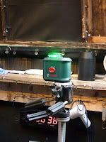
The first image shows the Bosch 360° laser level on my old Bogen video tripod. I bought the Bogen secondhand over thirty years ago. The paper scales have lifted over the years but the tripod still works as new. It is heavy but sturdy.

The laser level has an internal pendulum so is self-levelling over a limited range of base tilt. The pendulum is cleverly locked when the power switch is set to off. Making the device rather more robust than some examples. A Mode button, on top, turns the vertical, laser line on and off.

The bright green line travels right around the dome except for where the big mounting casts its shadow. This just needs the tripod to be moved to one side to throw a line onto the missing bit. This tool is absolutely invaluable if  you are building a dome from scratch. Or setting an existing dome up on its rollers. Normal people use them for laying bricks, putting up wallpaper or setting tiles.

You would not believe the hours I have wasted trying to establish the flatness and level of my own, dome roller ring. The 360° laser level gives instant confirmation. Leaving nothing to guesswork. 

The second image shows the green line projected on the edge of the base ring. Even in daylight the line is very bright, sharp and clear. Tests indoors, over much longer distances, 15+m, showed that the line expanded to 2mm. Still easily usable because it remained that width over the entire length of the far wall.

I have tried 3m long, straight edges, builder's levels and water [hose] levels and I was always unsure of my results. Straight edges are never truly straight. Builder's levels only rarely, perfectly accurate. Water levels have a near invisible meniscus [in clear hosing]  to confuse matters. The sheer weight of the water-filled hose was always a serious problem.

I would have to support that weight with prussic loops of cord and hanging screws. I spent more time refilling the hose with water, using a small funnel and a jug, than checking levels with it. The slightest change in level of one end and the water would fountain out of the lower end!

*


22.12.20

22.12.2020 RA drive mods underway.

 *


Tuesday 22nd mild, 46F, misty and overcast with early drizzle.

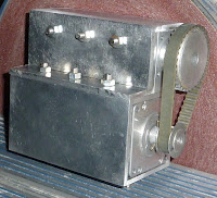
I have started work on reinforcing the RA drive assembly. The M6 screw holes need countersinking inside the motor box to allow the heads to clear the motor. This process is very time consuming and there are lots of them. 

The images show the progress so far. All firmly bolted together. The assembly was posed in the correct orientation. It hangs below the large, 10mm motor support plate from the two, projecting screws at the top.

I still have to make a new, front motor plate. This plate helps to lock the motor to the rest of the assembly. At present the motor is just inserted into the box section. There are flour threaded holes in the motor end plate and a further four in the worm housing. Providing a solid connection between the two when the plate is in place.

I have a whole selection of small grub screws now. So I can reduce the diameter of the larger [32T] timing sprocket hub in the lathe. It wants to be smaller than 28mm. So that the motor plate can act as a bearing stop for the outer race. The old motor plate had a very large hole, to clear the generous hub. Which did nothing to restrain the bearing.

The angle profile stiffener I had made for the tail end of the motor no longer fits the new layout. So it will have to be remade from scratch.

The bearings shown are the old ones and just pushed into place for these photos.

Grr! The drive belt is now so tight that it stalls the drive motor! I was tempted to order a longer belt from Rip-off Spares.dk but they want 85DKK or £10.38 for delivery of an item weighing just a few grams. I'll keep looking for a Danish stockist of T5 x 10mm belts in 265-270 length 52 or 53T.

I have now ordered several different, slightly longer belts, a smaller timing pulley and a microswitch from a German dealer pretending to be Danish. Rather than a UK dealer only pretending to be Danish. The prices were much lower. As was the postage. Delivery in the new year.

I spent some time on the lathe reducing the hub of the 32T sprocket to 27mm. Then fitted shorter grub screws. Any idea of moving the worm across via slots for the fixing screws would have made a motor plate impossible.

Later I re-checked the dome base ring with the laser level as I turned the dome. The problem seems to be the dome base ring is not flat. Since there are gaps between the tops of some of the rollers and the base ring only some of the time.

*

22.12.2020 Nocturnal insights into heavy dome assembly and handling.

 *

Tuesday 22nd 

As I was lying there, half awake, waiting for a suitable time to get up, I had some new insights into my dome project.

Most of these ideas relate to the considerable weight involved. About 500lbs or 220kg for the entire dome. Each segment weighs 70kg or 160lbs. This weight must be fully respected and planned for. I presently have no idea if each segment can be safely manhandled while working alone. So I need to pre-plan how assembly of the basic [3 segment] dome will be accomplished.

If I cut away an observation slit this will seriously weaken the central segment. So I thought of threaded rods [studs/all-threads]. These can temporarily bridge the large gap of the slit in the central segment. To replace the short bolts which usually hold the segments together. Nuts and washers will still clamp the individual segments together. While the distance between the segments will be fixed by the rods. Hopefully, regardless of the observation slit's absence from the previously, self-supporting structure. 

The spacing between the flanges at certain bolts holes should be measured, marked and noted for the studs before the slit is cut. The studs could be fitted at intervals during the actual, slit cutting process. To avoid hindrance of the jig saw but closely following it to secure the structure against distortion.

If the dome can be safely lifted by a ring on top. Then it can be safely lifted by a jack inside the dome. It just needs a stable, pyramidal, timber "rise and fall pier" in the centre. So that the jack's considerable lifting force can be safely applied. 4x4 timbers make sense for building the pier.

A 4x4 timber "piston" can be restrained upright by crossbars in the pier's structure. So that the jack can remain down low where it can be most comfortably applied. It might need nothing more than a car, scissors jack for the lift. These have both the capacity and considerable linear movement. 

Once lifted the entire dome can be rotated for work to be carried out on the lower edge. Once the observation slit is cut out there will be far less strength at the top of the dome until reinforcement has taken place. So timing of each building stage is important. Lifting becomes more difficult after the slit is cut out. It would need long strops or ropes reaching down to the base flange. 

The dome base ring will be of laminated plywood bolted around the existing, moulded flange. The dome rotation rollers will support the entire dome by this base ring. So it needs to be both flat and strong. It follows that the dome ought to be assembled on top of the pre-levelled ring. Which will ensure the segments are level when everything is bolted together. Epoxy resin might be better than wood glue for "structural woodwork." 

The laser level will be ideal to set up adequate supports for the dome base ring before lowering the dome on top.

The base ring can be initially cut oversized in outer diameter. Then trimmed back afterwards using a flush router bit. A suitable depth of material [plywood] needs to be built up at the edge of the fibreglass. To allow a weather skirt to be fixed to the dome's lower edge. The skirt will be vulnerable during the big lift of the dome onto the building. So is best applied after the "main event."

The donor igloo's, wide doorway needs to be strongly bridged by the base ring. To avoid it spreading wider after cutting out the observation slit. This need must be kept firmly in mind as the base ring is laminated together from limited lengths of plywood arcs. The [metric] 4x8 sheets set the maximum limit on arc length. So the actual position of the butted ends of these arcs ought to be considered.

The observation slit needs serious reinforcement to avoid weakness at the edges. I thought of making solid timber flexible by multiple saw kerfs. Though multiple laminations of thinner material might be stronger. 

Birch plywood strips could be built up on the inside edges of the slit. Being held by spring clamps would be easy after the slit is cut out. This reinforcing strip will then be screwed at short intervals to the edge of the slit to stiffen the central segment after its major surgery. 

Only then can both ribs be applied for the bi-parting shutters to open and close against. The laminated plywood rib arcs will further help to reinforce the edge of the slit. These ribs will carry on down from the zenith to the base ring at the doorway. Further reinforcing the base ring at its most vulnerable point.

A thicker board will space the slit ribs on the base ring and beyond them to the dome itself. On either side of the doorway cut-out. The curved triangles, outside the slit ribs, can then be filled in. I thought I could laminate suitable filler panel moulds on the dome'¨s external surface.  Though these area will be lost behind the open shutters during use they will be highly visible at all other times. 

Fibreglass matt and resin could be applied inside the dome to tie in the slit ribs more securely. I am not sure how securely GRP will adhere to the inside of the dome. It might have protective coatings applied during manufacture. Perhaps it just needs a wipe with acetone where resin is to be applied? I ought to ask the manufacturer about this.

I keep wondering if glass matt or cloth could be laminated between layers of plywood for increased strength and stiffness. Though this would need suitable temperatures to harden properly. So it will have to be put off until [probably] late spring. With global warming it is possible for it to be warm much earlier than usual.


*


21.12.20

21.12.2020 A tilting [shade net] screen of invisibility!

 *


I have had a completely mad idea for concealing the brilliant whiteness of the new dome. The donor igloo is claimed to have a solar heat reflecting, white finish! Presumably titanium white. White doesn't get much brighter than this! Ideal for solar imaging. Where thermal effects are highly undesirable.

Now imagine two, hinged and counterbalanced arms. With pivots on the east and west sides of the building. Add almost opaque, pro-quality shade netting. Stretched over a frame only in front of the dome. Facing south, the house and the distant road. The screen remains in place only when the dome is not in active use.

Release a cord and the netting screen will effortlessly lift out of the way of the telescope's light path. Carried upwards by the hanging counterweights on the east and west, see-saw arms. Providing instant invisibility and adjustable, solar shading combined! 😎

The frontal net frame could be curved to follow the dome. Helping to reduce frontal area to wind loading. Perhaps a lightweight PVC plumbing tube frame for lightness? It could even be curved into a semicircular shape if it was PVC pipe. This would also help to reduce the net's own visual impact over longer distances. It would be "tree" shaped. 🌳


*

21.12.2020 Keep that dome rolling.

 *

Monday 21st. Another grey day in prospect. No sign of Jupiter and Saturn close together yesterday evening. You wait 800 years and then cloud comes along. It's just like the total solar eclipse expeditions of the past. They'd sail off in hope of capturing vital information. Then it would be cloudy at their carefully calculated site on the other side of the world after months of travelling and preparation.

I am expecting the 360° laser level in the post. So I can try that on the old dome. I have never been able to confirm the individual heights, or levels, of the 180mm [7"]dome rollers. Hopefully I shall finally be able to do so now. It will be good practice for the new dome ring. 

I should have taken this image with the slit open for more light but it wasn't possible because of the weather.

As soon as it arrived I quickly unboxed the laser level. Then fixed it on my old video tripod with rise and fall, pan and tilt head. Set it up on the observatory floor and quickly levelled it. Switched on and enjoyed instant confirmation of the dome's base ring level. The green line was astonishingly bright, sharp and remarkably useful. 

When there is a change in level of the dome base ring, on the rollers, it tries to climb uphill. Which momentarily increases the resistance to turning. There does seem to be a small difference in level of the tops of the eight rollers. One particular roller is 1/4" high. Now I should really rotate the dome to detect if there are any changes in level of the dome base ring. 

I wish I'd had this amazing tool when I was building the original observatory. Though this model of the Bosch 360° level has only been released this year. They used to have red lines but the green is clearly superior. The human eye is most sensitive to green. Red is not.  I have struggled with a red laser range finder in seeing if the distant spot is on the target surface.The new level is self-levelling via an internal pendulum. I measured the laser line as only 1mm wide at 5' from the level. Ideal.

On the trolley front I have made a proper 2.2m radius bar. This is to confirm clearance of the nested segments from the jockey wheel jacks. It would be a bit silly if I couldn't fit them on the trolley when they arrived.

I set up a few tall items around the newly marked 4.4m circle and was shocked how large it seemed. It was worse when I stood a length of timber on end at the centre to represent the height. I can see the pole at eye level when seated at my computer in my upstairs window. This thing is going to be colossal! It is going on top of the [expanded] building! Eek! 

I ought to get some 3/4" plywood to make curvature templates for the building and the foundation blocks. With the worsening virus toll some shops are going to be closed until after the new year at the very least. I have no idea if that applies to the builder's merchants.


*

20.12.20

20.12.2020 A trolley at play carries the segments away.

 *

Sunday 20th overcast again.

Still playing with different ideas for the segment transporter trolley. I want to triangulate the frame using minimum materials for lighter weight. While providing widespread support for the semicircular, stacked segments, base flanges. 

Will skewed halving joints unduly weaken the 2x4s? If they stay full depth they end up 8" deep even without the minimum ground clearance added by the jacks and jockey wheels. About 6".

The image [right] shows one option. The curved load is spread over five points. Each carrying 100lbs.With the double, jockey wheels out at the edges for maximum stability and even load distribution.

The grey line marked 3.9m shows the foreshortened curve caused by the dome's cutaway doorway. The segment is still safely supported by the frame.

The image [left] shows the actual mock-up. Because the jack clamps have a minimum height they must be bolted to the upper timber pieces. I am trying to resolve the need for wheel castoring in turns. The tyres will strike the lower timber pieces unless the jacks are raised considerably. 

The cord on the ground is a rough attempt to show the dome's edge curvature. I am striking a 2.2m radius from where the crossbar is resting on the longitudinal 4.4m bar. I tried using a hose but it was stiff with cold and held onto its coils.

There is a danger that the nested segments will not fit onto the trolley frame because of the upright jacks getting in the way. The nearest parallel bar can be moved away from the longest bar [towards the camera] to provide more room. At the expense of reduced area of support. A plywood top skin on the triangle nearest the camera would help. 

Another trolley design [image right] with additional triangulation where the dome segment curves will rest. The new braces offer opportunities for jack clamp fixings at a larger radius and wider track. While avoiding potential conflicts between the segments and the jacks. 

I had enough materials, nuts and bolts to build the entire trolley but decided to leave it overnight. I may have better ideas and there's no point in having it lying or standing around in the garden. It is not as if I have even had confirmation of my igloo order. Let alone an expected delivery date.

The mock-up of the newly reinforced trolley is shown at left. I sawed one 3m length of 50x100 [2x4] in half to make it more realistic. By then it was too dark to perch on top of the stepladder for a wide angle shot. So you'll just have to imagine it looking prettier than this. 

I have found a forgotten box of 8" coach screws to hold it all together. Plus some others for holding on the jockey wheel clamps.

This thing is absolutely huge! 4.6m long x 2.5m wide. This is just a transporter for the nested dome segments. To get them home from an expected dumping on the verge. Over 200m from my home at the far end of the shared drive. 

The ground is still covered in spilt, self-compacting gravel. I will have to rake and brush it away. Before it gets trodden everywhere.

*


19.12.20

19.12.2020 Yo-heave-ho!

 *

Saturday 19th 42F, occasional weak sunshine but  mostly cloudy. More rock heaving and shoring up the observatory pad to the west. Followed  by yet more shovelling of self compacting gravel into the wheelbarrow. It looks as if there will be plenty of compacted gravel space around the concrete blocks now. 

No point in taking any chance with the blocks lifting out of the ground during severe wind storms. [However unlikely.] So I wanted the whole pad to be well oversized for the increased footprint. 

I'll lose the present path around the building but never really used it. Not once the grooved, plywood cladding was screwed into place. Which is easily managed from a ladder planted outside the gravel pad.

I have decided to build the dome transporter trolley out of 2x4s on edge. I shall need the ladders for the building work. So don't want to have to buy new to replace them. The ladders would also be far more bulky inside the dome. When I want to be moving about freely in there. Without tripping, nor banging my shins on the supporting cradle/trolley.

The reinforcing bar in the middle of the full width trolley [image below] is probably excessive. Unnecessary for local movement and support during the modification work. The wheels will be out under the edges where the loads need to be properly supported. There is nothing to support in the middle. 

Triangulation can be achieved out at the corners of the frame. Either with struts or plywood sheet. Leaving the space inside largely unencumbered. The natural curve of the dome will ensure that I do not need to be standing out near the edges. The triangulation struts [or ply] could be placed to increase the supported area of the ground flange at the dome's rim.

The wheels and their jacks could be placed inside the dome's perimeter. To better protect them from the winter weather. I found these budget jacks stiffened up when fully exposed over time without regular adjustment. The critical screw threads, just under the crank handle, could be protected by a small, inverted bucket but do look rather "untidy." The crank handle is too bulk for a smaller cover. While the jack collapses inwards without the handle.

I now have four sets of the double, trailer jockey wheels, jacks and Q/R clamps. Claimed 500kg load capacity each. They also claim the double wheels do not dig holes when moved about on soft ground. As happens all too easily with single jockey wheels rotating on the spot. I made sure to buy wheels with solid tyres. Pneumatic tyres are a real pain despite their lower rolling resistance. 

I also bought 6x 3m lengths of 50x100mm [2x4"] timber for constructing the trolley. There is a slight complication in that the dome is shorter in line with the segments. This because of the open doorway. Holm and Laue list it as 3.9m long. With the whole dome at 4.4m wide. I had better ensure I can support a narrow crescent of the correct [shorter] length of loose segments. A longer frame might let the ends of the segments drop right through the trolley. 

I still haven't a clue how the dome will be delivered. Nor even how to load the trolley. Would they rely on the driver to manhandle nearly 500lbs in the absence of a tractor or fork lift to unload the lorry? That would surely be rather amateurish and well outside of normal working and safety conditions. This is not something I want to discover on the side of a main road. With racing traffic right on a blind corner!

The remains of the latest, trailer load of gravel has been dumped in a neat pile near the building. To free the trailer for more errands.

The early evening stayed clear for a brief moment before rain spattered the windows. Saturn and Jupiter were towing the bright, crescent moon. Like a kite, across the southern sky. Warmer and dimmer Saturn and brighter Jupiter below, were just clearing the distant trees. 

My first and probably last sighting of the pair. Tomorrow they are expected to be closer for the first time in 800 years  but, of course, it will be cloudy. An American advertising agency, masquerading as a newspooper, called it "the view of a lifetime." Which might well have been true. If we all lived that long.


*


18.12.20

18.12.2020 Making enough room.

 *

Friday 18th and a grey overcast again. I have spent the morning shoring up the north side of the raised observatory, self-compacting gravel pad with rocks. This is prior to adding more gravel. This material is remarkably firm but can be locally disturbed by heavy rain or repeated drips from the veranda. A covering of pea gravel solves this problem nicely, once the surface is levelled.

A flat area in the back garden/parking area has had the new dome circle roughly marked out with small stones. Just to check exactly how much room I really need. A surprisingly large footprint! There is a long wait for it to become warm enough for outdoor fibreglass work. So the dome could be sitting there for some months. Fortunately there is plenty of room to turn the car around despite the dome "workshop" circle. The trailer will happily sit on the opposite side of the dome "roundabout" until needed.

My plans for a low, mobile, dome carrying trolley, with trailer jockey, wheel jacks, will allow the dome to be moved about at will. The last dome sat on fixed stands while I built it from scratch. It seemed considerably smaller. Being able to move the dome about will make it easy to change its location at a whim if it proves necessary. Perhaps to place it in bright sunshine to harden the GRP?

Not to mention easy rotation to point the "doorway" out of the wind. Or into the sun for more working light. The dome will provide its own weather protection as I work. Unless I cut the observation slit away before I have the shutters ready. That would be rather silly. Even though I do have plenty of tarpaulins.

Once the observatory building, wood work is completed I could lift and finish off the dome "upstairs" in its final position. This would mean working on reinforcing the slit from stepladders resting on the upstairs observatory floor. The observatory's wall height would be added to the dome height. Instead of standing more safely down on the ground with the dome only slightly raised and adjustable. The semicircular doorway is already 1.4 meters high. So jacking it up will make entry even easier.

Not a huge deal to do GRP work "upstairs." Because I have numerous and sturdy, builder's stepladders. Though my memory is still sharp on the difficulties of fitting the bi-parting shutters on the dome when it was up high! Access to fit the holding screws to heavy duty drawer slides was a nightmare. Worth keeping firmly in mind with an even bigger dome and even heavier shutters.

The hinged, folding, builder's stepladders, with stabilizer bars across both sets of feet are heavy but very solid. Not the usual, flimsy things intended for indoor use and absolutely lethal outside on soft ground. I even use paired stepladders with my chain hoist for heavy lifts like the mounting. 

The crossbars at the feet are superb for stability on smooth surfaces. I just lash a pair of crossbars together with the stepladder straightened out. Then hang the hoist from the paired top bars. Four splayed guy lines, using trailer ratchet straps around the dome support roller brackets, provide all the stability one could wish for.    

If I leave the dome intact the area around the [supplied] top lifting ring remains at full strength. It is intended to be repeatedly lifted that way by farmers using front loaders and tractors fitted with front buckets. If I cut the observation slit away, when the dome is still on the ground, then I would have to rely on strops for the big lift. Major decisions to be taken in the future. Lifting the fully completed dome would [probably] be far wiser. 

This afternoon was spent shovelling yet more self-compacting gravel into the wheelbarrow. Then trundling off to dump it around the edges of the observatory building pad. To be stamped down to firm it well. It had rained hard on the steeply sloping heap at the gravel stockist. So it weighed a ton and was very difficult to shovel it out of the trailer. It has been quite a hard day altogether!


*

17.12.20

17.12.20 Igloo home transporter.

 *

The other day's concrete block, delivery fiasco was a real wake-up call on heavy deliveries. The igloo/dome is very likely to end up on the kerb or verge. So I am resorting to a flexible form of self-built transport for the igloo segments. Just in case. I don't want them to be sitting on the side of the road for hours while I frantically build a means of transport to get the "dome kit" home.

I probably want a long, open frame trolley with trailer jockey wheels at each corner. The inbuilt jacks will allow me to lift a heavy pallet, or nested segments, from the kerb/verge. A boat winch will aid loading on short ramps. It needs a wide track to cater for the considerable curve of the segments. The segments rest on a narrow flange, 2+ meters wide x 4 meters long. A semicircular arc with "fresh air" in the middle.

A few, bolted together lengths of 2x4 should provide enough strength and stability. Fine for safe transport along the 200 yards of the gravel drive. Moving them around the "parking area" where I usually work, will be far easier with such a trolley. I can even move and rotate the completed dome as required. 

The three segments weigh 220kg or about 73kg each. Which equals 480lbs or 160lbs each. So are beyond the comfortable lifting capacity for most septuagenarians without winches or levers. 

Even better, I could use two widely spaced, builder's ladders with jockey wheels attached. Ladders are low, light and very strong. The jockey wheel mounting brackets can be simply hooked onto/under the sides/stringers/rails/stiles without modifying the ladders. Then the whole lot can be jacked up for ground clearance.

The full dome footprint at 4.4m Ø can be easily catered for. Simply by widening the spacing between the ladders. Ladders are thinner than 2x4s at about 75m or 3" thick. Making loading onto the ladder "trolley" even easier. I have a handy pair of ladders at 3.3m long which would do the job nicely. 

The image [Left] was "borrowed" from Emma Robert's Twitter account for illustration and education. The sheer scale of the nested segments is obvious.

Emma Roberts, the UK dealers for Holm & Laue Igloos was very helpful in replying to an email asking for information. Emma kindly informed me that igloos can be ordered without the usual roof vents. Which would be very useful. Because I'd only want to block them off anyway.

Anyone in the UK who is interested in buying an Holm & Laue Igloo for building a large dome [or any other reason] should contact Emma. She has a useful, well illustrated presence on Twitter:

Emma Roberts (@Emmacalfigloo) / Twitter


*


16.12.20

16.12.2020 Swing that ring on a scale drawing.

 *

I am continuing to picture the new building layout relative to the original observatory. Though my desire to avoid expansion on the northern side does increase the complication. 

Fortunately the new building is larger than the old. Should I leave the two support posts nearest the shed untouched? Then work around them? That makes good sense. Their angle to the shed wall actually helps the cause. By swinging the new building's footprint more southwards.

The rest of the building falls safely outside the original form. So I can keep adding new foundation blocks. Then just ignore what lies inside that circle. At least for the moment. With more support posts than before and closer together. 

My thinking is that these will provide increased anchorage against gales. While simultaneously resisting sinkage. Though on the last dome I lifted and dropped the concrete footings in their holes repeatedly to firmly compact the gravel.

I just hope I can get in and out of the existing door! Post spacing will be 98cm instead of 121cm. That is only 23cm difference. There will just be more posts spread around a larger circumference.

Ideally the panel nearest to the shed and both of its supporting posts remain firmly in place.  The new building's shell will be slightly more rounded and further out. By enough, not to cause interference between the two structures.

It has occurred to me that I could use pairs of bolted or screwed together 2x4s, instead of sawn 4x4s for upright posts. They would be considerably lighter to handle. Provided I can get them in the correct length [4m] and straightness. They are not subject to weathering nor ground contact. So normal timber quality is fine. 

I have bought and drawn in 12 new support blocks. Which places them slightly closer together than the original building. Which also means there is only room for a single door rather than the present rather narrow double. Of which I only use the right side making it even narrower. 

I made it double to allow large objects to be brought in. A more normal width, single door would do just as well. I can still make one out of a single sheet of grooved cladding plywood and internal spacer battens.

12.55 and the first glimpse of real sunshine in what seems like two weeks! Without the RA drive I'm not set up for imaging. I have spent the entire morning measuring and endlessly redrawing to scale.

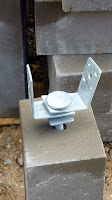
It took some time to temporarily fit the steelwork and remove the concrete blocks from the trailer. They are slightly tapered towards the top. This is intended to resist lifting out of well compacted ground. Roughly 50x20x20cm [19"x8"x8"] and weighing about 36kg each with the steel brackets. Which makes them much easier to handle than as bare blocks.

I have just heard from the calf dome stockists with a tentative price. Plus delivery, of course. Which will have to be on a smaller vehicle than yesterday's 40' container, articulated lorry. I must avoid having a massive pallet sitting on a blind corner in the the middle of the road! A rigid lorry with a tail lift and pallet truck is vital. They can manage the drive without a problem. How can a heavy, 5m long pallet be unloaded with a fork lift truck? Surely it would have to be loaded into a curtain sided lorry? Or, it would have to be lifted and rotated on the raised tail lift.


*


14.12.20

15.12.2020 On the Level.

 *

Monday 14th/Tuesday 15th. I have been thinking about the big stepladder and how it could be moved nearer the wall of the larger building. That might free up some more floor space. Ideally the trapdoor/stairwell should be in the SW of the observatory floor. This is where there is least foot traffic with a big solar refractor. Particularly in the mornings when the seeing [conditions] are usually at their best.

The problem was the fixed slope [70°] and sheer size of the ladder and its handrails at 60cm wide. The huge, timber pier and its widely splayed legs forced me into a fixed position. Oh, and the need for floor joists didn't help at all. 

In retrospect, I had little real choice over ladder position. Though I could have cut the joists and boxed around the new hole it felt like a fudge at the time. It might also have weakened the structure. I'd much prefer a tangential ladder but there was [and probably still is] simply not enough room.

Guess who has been worrying about setting out the [bigger] dome and the building/dome base rings?  I have no flat ground. Nor covered indoor floor surface. The top of the building will be high above the ground anyway. The dome will have to be packed up for working comfortably and safely underneath. I still have the adjustable, caravan parking jacks stored away just longing for a new purpose in life.

You'll just have to imagine my wasting man weeks going round and around the last dome and the top ring of the building. Desperately trying to get them both level for absolutely smooth rotation. 

Early on I bought a long length of clear hose to make a water level. Even that wasn't very satisfactory in use nor particularly accurate. Never underestimate the weight of water. The filled hose became so heavy that it was near impoissible to use until I had a proper floor. 

I was endlessly packing up the dome's support rollers and then taking the packing out again. Again and again over the last two years! I used several 3m long straight edges and my various builder's levels. Including a single spot laser level. Still indeterminate results around +/- half an inch or so. Who really knows?

So, finally, I have bought the [still imaginary] dome a Bosch self-levelling 360° laser level for Christmas. This throws a bright green horizontal [and vertical] line with an inaccuracy of under a millimetre. Not their most expensive model by far. Because the Pro models run into very silly money for a mere, amateur, project builder.  I only needed a continuous, horizontal and vertical line within a range of a few meters. So I bought the Solo head alone as I have umpteen tripods anyway. 

I shall be able to use the level to set out the rollers on the expanded building. As well as checking the plywood base ring for truth. This will be bolted to the rather small, moulded GRP, dome flange. To act as a wider and smoother track for the supporting rollers to run on. Not to mention my friction roller, crank-driven dome rotation system. Always within easy reach of my imaging chair. I don't even need electrodes applied anywhere for the dome to move effortlessly.

The new dome has unusual, external, upstanding joints. Which also have to be bolted together to make the three segments into a solid, white hemisphere. So, as well the usual silicone sealant between the flanges, I could apply a flexible, inverted U-profile. For cosmetic neatness and improved weather proofing of the flange edges. Which will only be partially covered by the shutter[s.] 

The concrete anchor blocks turned up today. In a vast, [but empty] articulated container lorry! No way to get that thing down the drive! The driver was just able to get the pallet off the road and onto the start of the drive with his pallet truck. Then I parked the car trailer alongside. Followed by 12 x 35lbs dead lifts off the low pallet and into the trailer. Only two neighbours needed to pass but there was just enough room for their cars. Now I need a rest!


*

14.12.2020 Footprints all over.

*


My latest thinking is that I should move the centre point of the larger building to the WSW. This will avoid the need for large quantities of gravel to make up the low ground to the north. Where the ring of concrete foundation blocks will need firm ground in which to be buried.

This is also the most difficult area to reach with a wheelbarrow. Which has to be steered around the octagon on a rather narrow path. With [untouchable] oak tree stems bordering the existing pad. My wife grew red oaks with very large leaves from acorns. The observatory came later. 

The remaining, slender oaks now tower over the existing dome. They do no harm and I have no interest in the northern sky. Much larger trees soar along the northern and western borders of our rural garden. It would take a team of professionals to deal with them safely. So they are left to fend for themselves. To provide an attractive backdrop and windbreak.

I should probably use the existing NE post of the octagon as a fixed, reference point. To be incorporated into the new structure. Around which to rotate the larger, circular footprint [via the arced templates] to maximise efficient ground use. The situation is rather like a large hula-hoop. One which can be rolled around the octagon's base at will. While remaining in contact.

The centre of the new dome will only move about 18" or 50cm from the original. I am using 4.2m as the new building diameter. This will provide a 100mm overhang of the dome's rim over the new footprint. 

It is obvious that I cannot dismantle the structural elements of the old dome before the new posts are safely in place. These must take over the load bearing and be tied into the original joists. Fortunately the veranda joists are just extensions of the main observatory floor. Some creativity may be needed to bridge any gaps.

The pier will also need to be moved to the centre of the new dome.I plan to rotate it to align with N-S. Something I overlooked in the original dome because of the need to keep the southern doorway clear.

The area of gravel in an arc from the west right around to south-east of the octagon is the most stable and well established. While the ground over the northern arc falls away and has by far the least exposed gravel pad width. Requiring much larger quantities of gravel to bring it up to a useful, building pad level. 

I have considered using field stones to reinforce the sloping edges of the pad at a later date. With luck, this common agricultural "nuisance" material may be the cheapest bulk option to provide improved solidity. At the cost of considerable physical effort. There are several large heaps of stones collected from the fields in the area. Easy access from the road too. If I can get permission from the farmer.

A disappointing trip to the local gravel man as he was not at home this morning. I will ring him later to confirm when I can collect another load of gravel.

I have had confirmation of my order for the concrete foundation blocks. Delivery is now for tomorrow 15th. With a warning that the near 500kg, loaded pallet might be left at the kerb. Over 200 meters away! I have emailed them requesting home delivery and had a positive response.

*


14.12.2020 Day 2 of budget 4.4m dome project. Setting-out templates.

 *

Monday 14th Dec. No ill effects from yesterday's "groundworks." I thought I'd be aching all over today after the unaccustomed exercise.

The image [Right] is a scale plan of template arcs for setting out the larger building boundary. The idea is to maximise the dimensions of each arc. While keeping material usage [and wastage] to a minimum. Only four arcs can be safely cut [lengthways] from a metric 4'x8' sheet. [1220x2440cm]  

All of the arcs are drawn at the same radius inside and out. So they can be used as positioning templates both inside and outside of the desired post/foundation ring. Whichever is most appropriate should a tree stump get in the way. Several saplings have had to be chopped off since the original observatory building was erected. Rather than dig them out and badly disturb the well compacted gravel I just left the stumps to rot.

Are only four arcs enough to accurately set out the ground base ring of concrete anchor blocks? Cutting the arcs across the sheet might seem more economical due to reduced wastage. Though short arcs have to be placed end to end to achieve the same overall circumference. Each joint cheerfully adding its own potential for inaccuracy. My own experience suggests that longer arcs are very much easier to align at each joint by eye. Fewer joints = fewer errors of alignment.

No attempt should be made to fix the templates together permanently. They do not have the strength to support each other. They could be drilled at each end for a single, large, alignment nail. [To avoid repeated losses] To join them loosely together after laying them all out on a flat surface. This will speed repeated alignment in use.

The image [Left] shows the original foundations [May 2017]  for the octagonal observatory building. Showing the concrete foundation blocks in their holes. Some of the large boulders unearthed during the [entirely manual] groundworks are also shown.

The overlapping template joints should then be clearly marked 1 1, 2 2, 3 3, etc. I used pencil on the last dome project and it was almost pointless. Clear markings with a magic marker will save hours of searching for newly invisible scrawls. You wouldn't use a marker on visible surfaces but it is excellent for hidden ones. Or where it doesn't really matter.

The next decision is how thick the plywood [or other sheet material] wants to be for adequate strength and stiffness in all planes. No point in making thin arcs if they are too weak to support their own weight. No point in thin material if they snap under their own weight when lifted from the ground. Or are too weak to hold the curve when flexed along their length.

Can these arcs be incorporated into a dome base ring? Or observation slit ribs at a later date? In order to save the considerable material costs of [say] 3/4" thick plywood. They will already have the correct outer radius. So choosing suitable materials could more easily make them dual purpose.


*

13.12.20

13.12.2020 Day one of the 4.4m budget dome project: Gravel & concrete!

 *

After the endless monologues I have actually made a physical start. One car trailer load of self-compacting gravel has been distributed around the edges of the existing observatory "pad." To enlarge it by about a meter [3'3"] all around the precipice. 

I used a builder's shovel and wheelbarrow to ferry the heavy material the few yards from the car trailer to the "building site." Then stamped it into place with my boots to firm up the edges. It doesn't seem to move much, at all, after this treatment.

Self-compacting gravel is a mixture of sand, gravel, small stones and a little clay to bind it solidly. It is easily identified, at a gravel stockist, because it has an almost vertical critical angle. The critical angle is the maximum slope a granular material can tolerate. Before it flows or rolls naturally downhill. Stamp on a steep pile with a work boot and the footprint remains. On sand or ordinary gravel it will usually flow away from the impact site. Particularly when the material is dry.

Self-compacting gravel is best kept slightly damp for maximum hardness and continuing resistance to long term loads. [Like small building foundations.] This is easily achieved if it is laid on normally damp soil. The disadvantage with the stuff I buy is the ginger sand content. Which is carried across the lawn wherever I walk. A thin layer of pea gravel soon solves this problem where the gravel is expected to lie permanently on the surface. The gingeriness soon gets washed off the lawn by the rain. The Danes call it stabil grus. Or self-stabilizing [i.e. stable] gravel. 

Another trailer load should complete the space required for the building extension/expansion. Though I haven't expanded the area enough for a level path around the new building. This would require a whole lorry load! Plus a lot of hard physical effort. Given the drop off, from the edge of the existing pad I will defer a decision on further expansion of the level area.

The image [Right] from April 2017, shows the carport anchor blocks laid out on the original, imported gravel, octagonal, building pad. The proximity of the shed dictated the buildings position and the sheer quantity of gravel required. The covered space was sunken by over two feet [60cm] over much of its area.

I just ordered 12 concrete foundation blocks and brackets cheaply online with very low cost delivery charges. These are the same blocks as I used on the octagonal building and the pier [above]. They have shown no sign of moving or settling. Dimensions are 50x200x200 and their weight is 35kg each.

Thanks goodness I don't follow convention and cast a huge concrete pad the size of the building. Which would probably lie there forever. Any wind which can blow over a building with 500kg of reverse tapered concrete blocks, buried in well settled, self-compacting gravel, will damage far more than just my observatory. A cylindrical building with a dome on top has very little drag compared with a square one with a pitched roof.


*

13.12.2020 Maintaining new building roundness.

 *

Sunday 13th. Heavy overcast again. As a mental exercise I am continuing to think about methods of expanding and waterproofing my observatory. There is no pressure to read my random thoughts. I write them down because I find it helpful to iron out potential options and unforeseen drawbacks. This method allows lots of new ideas to pop into my head.

The latest image shows how a ring of 14 support posts could be erected outside the existing octagon. Spacing on an accurate circle could then be managed with external plywood templates cut to exact size. Though, even here there is ample opportunity to get it all horribly wrong. 

Plywood arcs in these huge radii are simply not stiff enough unless made very thick [and heavy.] I was using crossed planks fixed across 3 meter circles for the last build. Now add an extra meter in diameter or half a meter in radius. Without being allowed crossbars to maintain perfect roundness.

It should be obvious that I cannot stretch a line or [much better] a radius board from some imaginary centre within the existing building. Nor use a tape measure for that matter. There is the existing building's plywood cladding and the huge pier posts blocking access. As well as the eight upright, perimeter posts all getting in the way. 

So setting out the new post holes accurately is going to be a bit of a nightmare. It was difficult enough on bare gravel when I built the octagon. The bulky concrete anchors in their freshly dug holes simply didn't allow for micro-adjustment. Not helped by the hot and dry conditions which made the gravel looser than normal.

Yet another idea popped into my noddle. I could use a metal rod to measure the radius from the centre point of the new building. This would require only a small hole be drilled through the octagon's cladding. Specific post hole positions can be measured externally using the template arcs and a tape measure. There is absolutely no need to measure out to a particular post at exactly the required angle.

*


12.12.2020 As you were 2.

 *

Lifting of the completed dome is well within the capacity of a hired telescopic lift. They can lift tons and I'm not seeing more than 300kg for the complete and modified dome. 220kg bare, as supplied. Lifting height is an issue and the machine must have the necessary range. Including the considerable depth and convex curve of the dome and any free length of thr hanging strops.

Making the dome  modification on the ground is the safe and far more sensible option. Though I have no personal experience of driving one of these telescopic lifting machines. It would also need to be driven 20 miles in total. Much of it along narrow, rural lanes. My neighbour is skilled with many similar machines and tractors so might be willing to help with the actual lift. The old dome could be lifted down in one go but can also be manually lowered as manageable segments.

It would be possible to lift the complete dome onto a larger base ring by supporting it [temporarily] off the veranda. The joists are just below and can easily manage the weight spread over the old building's footprint. It just needs some props off the veranda joists up to the roller base ring. The ground posts can be added later. Or just the two or three posts in the SW-Western arc. Where the new footprint overhangs the most. 

Alternatively, I could ignore the existing building posts and build a ring of new posts. Just outside the old building, but offset to the west to match the new footprint. This would place it nearer the shed but would not impact the old building. Which could be partially disassembled once the new dome is safely supported. I'd still need to expand the [self compacting] gravel pad for the western and northern arc of new foundation blocks.

Despite everything, the new dome will cost a very small fraction of the retail price of a commercial dome in the size I am contemplating. 4.5-5m domes seem to cost £20k+! Given the price I have been quoted for home delivery of a 2.7m Pulsar dome and base ring only, I can install an entire 4.4m dome for not much more than the delivery charge. From the sole European, Pulsar dealer, next door in Germany. 

That did not even include erection on site. Just a pallet dropped somewhere on the 200m drive from a ridiculously large and expensive lorry. If it couldn't reach our gate then I would have to find a way to carry all the Pulsar dome sections the length of the drive myself. Thank goodness I didn't buckle and go ahead. Ending up with a dome which was far too small for my refractors anyway.   

*


12.12.20

12.12.2020 As you were!

 *

After all this thought, discussion, measurement, photography, examination on the ground, drawing and planning I have decided to enlarge what I have. The building will be expanded directly towards the WSW. The ring of 4x4 uprights will fall on the rim of the veranda in the WSW but will overlap elsewhere. The veranda floor boards can be removed individually to allow for this. While providing support until all these new posts can be safely tied into the structure. 

Moving the centre point of the building bodily towards the WSW will minimise the need for new gravel for concrete anchor footings. A few car trailer loads will provide all that I need. While safely maintaining the same overall distance of the building from the nearby shed. I was hoping to move it further away but can't see how.

My local gravel supplier only has a large, tipper lorry. Which cannot reach the building site. I have absolutely no desire to trundle back and forth with laden wheelbarrows. Like we did last time. 

That took several days after a local groundwork business failed to provide the promised shuttle service between the gate and the groundworks. Moving 20+ tons of gravel a little over 30 meters, entirely manually, is not the sort of thing most septuagenarians do!

The circumference of the new 4.4m dome is nearly 14 meters. So logically I shall have 14 concrete anchors supporting 14 upright posts. This will allow 14x half [8x4] sheets of grooved plywood for external cladding. The actual measurement between posts will be slightly less. Because I need the dome to rain safely outside the supporting building. So it needs to be smaller. Even on the angular points.  The angle between 14 posts is about 25°. I shall use one of the original uprights, nearest the shed, as my geometric, anchor point. Everything else will hinge on that particular fixed point.

The trick is to get all the new posts upright and on a perfect circle at ground level. The steelwork bracket on the tapered concrete anchors is not very user-friendly for lateral movement. Though they do provide height adjustment. Getting the anchors in the right place in their holes in the ground is another problem. The hole has to be made too big and nicely flat on the bottom. So the heavy anchor can be levered about for position. Not easy in two feet deep holes crumbly, self-compacting gravel.

I shall need to make curved, [external] plywood templates for the post circle. Then get them the correct distance from the new centre of the building at the correct spacing between them. They can be temporarily braced with screwed or clamped planks. Before the 2x6s are mitred to length and angle to fit and then screwed between the posts. 

Following an accurate circle at the top too. For the plywood top ring on the building. Which is where the support and dome rotation rollers will sit. It obviously helps if the ring is truly round. So that the dome doesn't rub on it during rotation. A short skirt will probably hang down from the dome to keep wind blown rain out. I used a plastic upstand on the present dome and it rubs on the rubber skirt at times during rotation.

All that I have discussed will allow me to continue to use the present observatory until the dome can finally be replaced by the larger one. Which can only happen after warm weather in the spring. Which will allow GRP reinforcing work to be done along the observation slit, plywood ribs on the new dome. That gives me plenty of time to consider how best to incorporate the new building with the old. Not least how and where to place the big warehouse ladder. If the building is wider the ladder need only be moved to the new, outer edge.


*