31.10.21

31.10.2021 Shutter, drawer slide spacers and droop.

 *

Sunday 31st 51F, mild, very cloudy and a bit breezy at times.  The clocks have gone back.

Today, I must space the lower drawer slides further away from the dome. The difference required is about 50mm. I have a choice. I can add a batten to the outer face of the slit base board. Or add a batten to each, lower, shutter board. 

The difficulty is deciding which choice offers the best access to the drawer slide, fixing screws. These screws are exposed. Or hidden behind small holes as the slides open and close. 

Having fitted the shutter boards only yesterday I should probably choose to space the bottom, shutter boards. Or I could make new boards out of scraps of 50x150mm. [2x6"]  I'll try spacer battens first. To avoid wasting timber. 

It was just as well I didn't make solid timber boards. I only needed about 20mm thick battens to push the shutters well away from the dome. 

There was quite a bit of unexpected work involved. All the screws had to come out of the slides to allow their complete removal. The slit base board had to be removed and raised. Then the battens fixed to the original form boards after they too were removed. Along with their fixing brackets. Another twelve screws each. Thank goodness for rechargeable screwdrivers and Torx screws! 

Only then could I reassemble the shutters and slides. Needless to say, the shutters do not yet open smoothly. They flex far too much. Enough that they can be open at top. While the bottom ends are still half closed.

Having fitted it all back together I made a disappointing discovery. The shutters have a 4" gap [100mm] in the middle when fully closed at the top and bottom. The outer, shutter ribs need to be lifted relative to the inner ones. Which means that the bottom boards have to be slanted within the shutters. Or the slides have to be slanted on the battens. 

I have seen this problem repeatedly while working on the shutters before the slides were fitted. Adding quite a small amount of packing under the outside ribs closes the yawning gap in the middle. There is considerable, negative, geometric advantage due to the ratios involved. [Negative leverage?] Imagine a wedge hammered into the saw cut of a tree being felled.

The problem is in discovering how much the outer ribs need to be lifted. I may be able to correct the gap by removing the slide screws and packing up the ribs. Then refitting the slides in the new position. A bit of extra lift will avoid repeating the exercise.

The gap problem may simply be that there is no fixing on the outboard ends of the bottom boards. I haven't fitted any brackets there yet. Relying, instead, on the massive inner brackets. Perhaps these brackets are flexing more than I imagined under the considerable weight of the shutters. The slides are also doing their own supporting. Though they are at the thinner, most flexible end of the 3-slide mechanisms.

Once I have the ribs packed up enough I can temporarily fix the boards with single screws through the outer ribs. Prior to fitting the brackets. I don't want to split the bottom boards by screwing into the end grain. There really isn't much meat at that end. So I had better pre-drill for self tapping wood screws. I have some sturdy but narrow brackets ready to fit.


*

30.10.21

30.10.2021 Dome shutter progress at last!

 *

Saturday 30th 51F, bright start, but rather cloudy. 

10.30. Set up for imaging in bright sunshine.

10.40 Now solid, grey overcast.

OMG! This means I have to work on the new dome!

I decided to double check the shutter alignment before proceeding. A 2m straight edge was laid across the inside of the observation slit ribs. Then I leveled it. A second, shorter level checked the level of the slit base board. I measured forwards from the straight edge to the inner edge of both, outer, shutter ribs. Some fiddling with prop levels and all was well.

This gave me a reference for marking and cutting out the right side, shutter, base board. I was just able to make the board out of a bit of scrap 2x4. [50x100mm] Then I could fix the bottom shutter slide to both boards. 

Though I have yet to fix the shutter boards to the shutters. This would be premature before the final shutter heights are fixed. My 360° laser level suggests that the slit, bottom board is about an inch low. [25mm] It should rest on top of the dome, base ring.  Which is yet to be completed.

The last image shows that I could probably lower the top drawer slides. Both shutters are too high relative to the slit ribs. There should be an overlap for basic weather sealing. The shutter slides limit the shutter's outward movement.

I was finally able to open and close one shutter supported only on the drawer slides. Though it was a struggle. Neither top nor bottom boards are properly connected to the GRP shutter covers yet. Which means that the cover is not providing its own [sheet] stiffness. Which would triangulate the shutters against lateral twisting. Not to mention securing the drawer slide supports. I do not want to drill any 10mm [bracket fixing] holes in the wrong place. Although they can be filled it would just add more work.

After lunch I shall make the bottom board for the other shutter. If it doesn't rain. We were promised rain in this morning's forecast. It didn't happen. We had some sunshine instead. Then it turned dark grey and stayed that way. It is very mild for the end of October. 53F at 14.00. The SE wind is rather variable.

It duly rained at 2pm. Just as I was about to start work again. I went out a little later as the rain stopped. Finishing the second shutter base board. Fixed the slides. Then found the shutters were too low. The ribs were rubbing on the dome before they were closed. They could not be lifted because they were fixed to the slides. The base boards were fixed to the shutter ribs with really sturdy brackets.
 
The shutters would no longer close. My first guess is that the shutter base boards are too narrow in plan. Easily checked and fixed tomorrow. It is dark now and the rain has started again. Pushing me back indoors. I can unscrew the slides from the base boards and add battens to their faces to check my theory. Pushing the bottoms of the shutters away from the dome should provide the clearance now missing. 


*

29.10.21

29.10.2021 Imaging and Lunt BF blue filter rinse.

 *

Friday 29th 50F, cool, very breezy but clear and bright. Seeing conditions show poor transparency and rapid thermal agitation and mobility. Occasional physical movement from gusts.

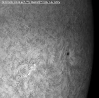
11.10 Struggling for clarity and detail. AR2887 still shows signs of flaring. The overall appearance has changed considerably from yesterday. With more, small spots arranged in a chain. Yesterday's filaments are also much changed.

I was becoming depressed and paranoid about loss of image quality from staring at the cloudy blue filter on my B200S2 blocking filter. Luckily the repair was effortless.


I used a watchmaker's screwdriver to remove the blob of silicone security thread locker. Then used a small pair of dividers to completely unscrew the filter holding plate. Then I tipped the BF gently over a Kleenex tissue. Both filter and retaining disk fell out safely into the tissue.

13.05 [CET] Finally an improvement in clarity. The PST etalon is still producing a ring of darker detail. On a diagonal from roughly 10-4 o'clock.

Online advice talks about various cleaning solutions for the Lunt filter. I gently used a new cotton bud and few drops of distilled [demineralised] water. Seconds later the cloudiness was gone. I used the Kleenex to dry and lightly polish the filter without pressure.

Then replaced the glass gently in the recess in the BF. Followed by the retaining disk. The dividers were used again to snuggle the disk onto the filter without pressure. 

I wish I could say the result was miraculous. It wasn't. The soft images today are entirely the result of the poor seeing conditions.

16.00 I tried imaging again later but the seeing conditions were impossibly soft due to thin, high, speckled cloud.


*


28.10.21

28.10.2021 Massive flares below AR2887! Plus AR2891.

 *

Thursday 28th 52F, overcast start, clearing to brief and still cloudy, sunny periods. Cloud steaming quickly from the south. Very windy!

11.08 [CET] First image of complex spot AR2887. Multiple spots and filaments. Not a great image. Captured through thin cloud using 1.6x GPC for wider field of view.


11.44 Far too much cloud and wind. Not one moment with a clear sky over the sun devoid of cloud. The wind keeps moving the telescopes.

12.00 Three small, bright flares suggest Ellerman Bombs.


12.27 Massive, complex flares south and SW of the main filaments and AR.


12.50 After the event. Still some flaring visible. There appears to be a cloud of "smoke" resulting from the flare.


13.05 Last before lunch. Wind worse than ever. 

The PST etalon is playing up again.


 14.02 After lunch. Still very windy.

14.30 Meridian flipped. Cropped.


 14.48 Sky is white where it should be blue.


 15.23 AR2891 on north-eastern limb. Bristling with energy.


15.23 AR2886 near western limb.


15.58


*


26.10.21

26.10.2021 Failed at imaging again.

 *

Tuesday 26th 50F, mostly overcast with some sunny periods. Despite wasting hours I failed to obtain a single image today. 


*

25.10.21

25.10.2021 Failed at imaging through cloud.

 *

Monday 25th 40-52F, sunshine and cloud. A triple cigarette lighter socket adapter has arrived in the post. This will allow me to have the dew/heat bands working, via a HitechAstro 4-way controller, as well as the DIY motor focuser. I hadn't expected these clumsy great plugs when I ordered these accessories. Mini-jacks are more normal connectors in my experience.

It was too cloudy for imaging this morning. 


*

24.10.21

24.10.2021

 *

Sunday 24th 50F windy from SW.  
 13.43 Afternoon imaging: Detailed, but off-band for H-alpha , I think.


14.30 I have been struggling with blocky images as they open in ImPPG.


*

23.10.21

23.10.2021 Afternoon imaging. AR2887 and dewing.

 *

Saturday afternoon 23rd: 49F. 14.24 : Strangely complex surface detail. Image still soft. 

Lots of heavier cloud has arrived! 

It was very odd. Hours after the objective cleared of mist the D-ERF misted over on the inside. The hair drier and hours of dew band had not helped. 

The three large thumbscrews make it difficult to wrap a band around the cell. Likewise with the objective cell. There is only the raised edge of the cell to which to apply apply heat. 

I wrapped two heat bands in series on the main tube just behind the cells. This took hours to clear the internal dew. Probably because the counter-cell is a thick ring of turned plywood. Which would insulate the glass and metal cells. Even with regular blasts of hair drier all around the cell rims. 

I don't have any aluminium large enough for a solid counter-cell. Perhaps I should be grateful because that would be a cold sink. Taking a long time to warm up after a cold night in the observatory.

Perhaps I ought to make a hinged door in the main tube. A little way behind the objective. Then I can blast the hair drier directly at the internal condensation. Without denying myself the ability to use heat bands on the main tube if the door was too close. 

Or, I could make an aluminium sleeve to fit closely over the cells. To provide a direct path for heat conduction from the dew bands. An overlying layer of insulation over the heat bands might also help. I have already lost more than enough potential imaging hours to dewing.


*


23.10.2021 AR 2886 central + AR2887 on SE limb.

 *

Saturday 23rd 40F, almost clear skies. Moon high in the west. I took a few snaps with digital zoom on my G9, Leica 50-200mm. Cropped and sharpened.

9.30. I plan to do some imaging now the tree shadows are off the dome.


Ridiculously soft images. The usual problem. The iStar objective is dewed over internally.  I wasted five minutes with the hair drier on the cell and main tube. To produce no visible change. I have connected an Astrozap dew band to warm the main tube behind the cell. 

10.30 44F in the shade.  Now it it has clouded over. Full power and 57F after five minutes? Now cooling! Connected a Kendrick. From 43F to 59F in seconds and warming rapidly. 68F. 78F. 84F. Dew disk shrinking to half aperture. 

10.40 Cloud clearing. Not a single, worthwhile image so far. Moved the thermometer sensor back to the Astrozap. 84F. 86F. 88F. 89F. The Astrozap seems okay now. 

Repeatedly retuning the PST etalon and re-focusing but the image just will not sharpen. A!3 and ImPPG can't improve things. Dew disk has shrunk to 2". 93F on both bands. Image improving.

11.07 [CET] 88F & 115F on the dew heaters. 2" thinning dew disk. First image. Still dreadful!  

11.23 First recognisable AR2886. More cloud.

11.40 Thin cloud continues to tease.

12.00 Double checked focus point with and without protective filters. 330mm from backplate. Confirmed PST etalon at 200mm inside focus. 130mm from backplate surface. Experimenting with rotation of BF relative to the etalon. Retuning and tilting. Cloud still teasing. Occasional improvement in clarity. Increasing thermal agitation. I keep processing captures but no real improvement.

12.12 Still adjusting.


12.22 Fitted PST BF to capture the large prom on the deep SE limb. The blue sky is white.


 12.40 Too much cloud!


*

22.10.21

22.10.2021 Barrel nuts.

 *

Friday 22nd 43F, heavy rain continues.

I have finally discovered the Danish name for a barrel nut. Tværbøsning.

These are useful fasteners where one wants a strong, mechanical fixing. Far superior to a wood screw driven into the vulnerable edge of plywood. The problem is a chemical reaction between different materials and rust. Almost all of these nuts are flash electroplated zinc over steel. Which are already rusting in the bubble pack in poor storage conditions. Using these out of doors is just asking for trouble if one ever hopes to dismantle the fixing. 

Stainless steel threads have a tendency to stick. Even when stainless nuts are used. Brass barrel nuts make sense. The material is easy to thread and machine. Now insert the bolt through an aluminium bar. The combination of different materials can lead to staining and electro-chemical reactions. 

Aluminium barrel nuts would work. Provided the thread size matches the loads.

Brass barrel nuts do not pop up in searches within Denmark. [Using the correct terms and avoiding AliExpress' online crookery.] So I ought to make my own. It is too wet to work out of doors. Not too wet to reach the workshop. 

I made an M10 barrel nut from a scrap of 16mm brass rod. I would have preferred a larger diameter to provide more shoulder to resist the considerable compression loads. 20mm rod?


*    

21.10.21

21.10.2021 Even darker and wetter!

 *

Thursday 21at 50F. Another heavy rain warning. Raining steadily, with a couple of downpours earlier.

The rain stopped at 17.00 yesterday so I went over to check the observatory. The collection trays on the base ring had accumulated some 10 gallons. Or two whole builder's buckets full. Some of the containers were full to the brim. So must have overflowed inside the building. 

I had closed the shutters on the new dome before the rain started. So there wasn't much sign of water ingress except ground flow. I haven't fitted an overlapping rain shield to the shutters yet.  

In an earlier post I discussed using barrel nuts to fix the GRP shutter covers to the ribs and top boards. As I was searching online for local stockists I was getting loads of suggestions with Danish sounding, business names. Every single one was a nonsense name cover for AliExpress. The Chinese direct sales business. It seems that even Danish sandwich vendors, with Danish sounding names, sell barrel nuts! [Via AliExpress!]  Let's see now: Months of waiting for arrival, VAT at 25% and post office, customs clearance charges of about £15 equivalent. I had better get an order off now! Not. 

Removed another bucket full of rainwater from the base ring containers of the old dome.


*

20.10.21

20.10.2021 Wet, dark and windy!

 *

Wednesday 20th, very dark, wet and windy!

Yesterday's struggle to open and close the shutters proved my worst fears. The drawer slides cannot control the shutters unless firmly mounted. I hadn't managed that. The slides must remain parallel to each other. The upper boards and lower forms were loose. My thinking being that this would overcome any misalignment issues while I fiddled. It didn't. The top boards need brackets on the inner ribs to tie the boards to the shutters and to boards. The  lower forms need the same. 

Given today's foul weather, with a heavy rain warning, I shan't be doing much to the dome. This will give me time to carefully consider my next moves.   


*

19.10.21

19.10.2021 Slit base board added.

 *

Tuesday 19th 55F, heavy overcast but dry so far. Rain promised after 2pm. Continuing for three days.

I have added a 50x200mm [2x8"] board to the bottom of the slit ribs. This will provide the drawer slides with a substantial support. It will also reinforce the slit ribs and base ring. I am using a timber off-cut in case I need to change anything.

The image shows the drawer slides clamped to the front [outer] edge of the board. The 50cm slides are too long for the 92.5cm slit opening. So the inner shutter ribs will need to be notched around the slides. The extra length is then ignored. Being lost inside the shutters.

Then, in theory, I can screw the slides to the slit base board and lower shutter forms. Allowing [again in highly optimistic theory] the shutters to open and close. I do not foresee the shutters being completely effortless without quite a lot of fiddling. 

Reinforcing brackets are optional. Thinner and stiffened with a rib or heavier material without.

I have a fallback option. To use cords and pulleys to open and close the shutters if they should prove uncooperative. I could even use weights to automatically close the shutters. Pulling on a cord would open them. The cord then being anchored to keep them open.  

The plywood dome shutters have performed well until recently. It being quite easy to open and close them from the bottom by pushing and pulling on the ribs. All within easy reach of the observatory floor. I should have reinforced the upper corners but didn't. So one has become loose and allows the shutter to twist slightly. Causing friction. I shan't make that mistake with the hefty GRP shutters.


*


17.10.21

17.10.2021 Drawer slide support forms.

 *

Sunday 17th. Overcast all day. I was busy elsewhere.

First I laid a 2m straight edge across the slit ribs. So I could measure the dihedral of the timber slide support forms. I then marked, planed and then sanded the right side form to be 5mm narrower at the thick end. This helped to reduce the dihedral. I shall repeat the exercise on the left former tomorrow.


*

16.10.21

16.10.2021

 *

Saturday 16th 44F, overcast with sunny periods promised. The sun broke through but it remained rather cloudy at times.

I had better be careful how thin I make the bottom, draw slide support forms. The drawer slide, fixing screw holes are widely spaced and few in number. Particularly on the thinnest, telescopic section, of three. So a reduction of one screw, per slide, due to inadequate material to seat in, could be a problem. 

The resulting forms tapered from 20mm to 65mm with 20mm clearance for the drawer slides. Sawn out of an off-cut of 50x75/ 2"x3". 

I may duplicate these forms and stack them vertically. Glued and screwed, the upper layer can be bolted to the GRP shutter cover. This will avoid conflicts with the drawer slides. Angle brackets will join the forms to the shutter ribs. 

I went ahead and added the drawer slides to the timber forms. The slides were slightly too long for the spacing between the shutter ribs. I shall have to notch the inner ribs to make room for the extra length. The ribs will not be much weakened and the notch will be invisible. If I notch the outer ribs then I would need to cover the gap. 

For the moment I just loosened the bracket bolts. The timber forms and slides have a slight dihedral. I can fix this when the tension has gone.

Or not. Let's say I take a wedge shaped slice off the straight edges of the forms. Making the thick ends slightly thinner. Then they will follow a straight line. I cannot add to the thin ends of the forms because there would be no room for the slides. There is too little room already.


*

15.10.21

15.10.2021 Imaging AR2882 and measuring the shutters.

 *

Friday 15th 48F, clearing from the north but breezy. Plenty of rainwater collected inside the observatory.

10.37[CET] First image today of AR2882 approaching the eastern limb. Rather modest transparency. 3/5? Some thermal agitation. 3/5? Poor imaging results. 3/5.

Beginning the usual focusing and etalon tuning rigmarole in search of improved images. 

11.00 Small clouds crossing rapidly from the WNW. The blue sky is white in the east. Image quality reducing. Back to working on the dome!

I took a photo looking down on the bottoms of the closed shutters. Then measured and drew the same with dimensions. I had stretched a cord tightly around the outer edge of the slit ribs for a reference line.  

The narrow space available for the shutter boards and drawer slides is obvious. Also how thin and asymmetric the shutter boards will be. These are vital components. Since they carry at least half of the considerable weight of the shutters. 

The drawer slide supports may need to be extended upwards to provide some extra "meat." This will leave room for bolting the slide supports to the shutters. These boards are shown in yellow.

Later I used the 360° laser to measure the squareness of the slit/shutter ribs in comparison with the zenith board. Measuring from the line projected on the ground, while the same line was simultaneously grazing the edge of the zenith board, proved a 2cm difference to the slit ribs. 

I am not sure how important this is. Or even if the laser line is accurate when projected overhead. I set the laser body on the base ring to minimize the projection height. The laser cannot project directly overhead. In fact there is a small protective cover over the top of the laser diode. 

This has been a priceless tool during this dome build project. Its internal pendulum assures the projected beam is level in all directions. The additional vertical beam is a great asset for ensuring perpendicularity and straightness of ribs and other components. 

The bright green lines are much more visible than red. Though I would not be very useful outside. Particularly in sunshine. It works superbly indoors or inside domes. For outdoor use I just wait until dusk. 

The prices of these tools seem to be falling steadily. Now costing about the same as many, popular, portable, power tools. I chose the Bosch Universal Level Solo 360 and have never regretted it. It uses four, ordinary AA batteries. Which seem to last for years. 

Here it is shown in the plywood dome checking the dome's, base ring level. As mentioned at the time: It managed this task instantly. Rather than the countless man hours I have utterly wasted using builder's levels and straight edges over the last couple of years. Or even a home made water [hose] level. Which nearly drove me to distraction!

The Bosch has a tripod bush and [very] cleverly locks its internal pendulum automatically when switched off. Its laser light flashes if its base support is not reasonably level. Though it seems quite tolerant in this respect. No extra effort being required beyond quite ordinary, common sense. I usually place it on a stack of timber off-cuts or plywood to adjust the height. Most importantly, it doesn't care if the surface, onto which it projects, is flat or spherical.


*


14.10.21

14.10.2021 Mounting slides on curved shutters:

 *

Thursday 14th 37F a cloudy day. 

I was too busy elsewhere to do much on the dome yesterday. Though I did make a 2"x6" board to fit one of the shutters. It was immediately obvious that I was completely off track. [sic] 

Any overlap of the board on the slit ribs would need the slit ribs notched to match. The drawer slide thickness would be added to the depth of the notch. So I need to keep the front profile but make the board much thinner in the horizontal plane. Which raises the serious issue of the freedom of the drawer slides on the shutters.

Now I have made a simple drawing to get my head around the problem of siting the bottom drawer slides. For simplicity the shutters are shown as tapered across their width. Rather than curved. [Which are much harder to draw with simple software.] 

The problem with the real shutters is rotation over the length of the shutter. There is nothing for the eye to fix on. Two highly asymmetric ribs are joined by a heavy, but flexible, GRP cover. There is no sense of straight or parallel.

What is clear, is that the slides must be brought well inboard [with curved shutters] compared with [normal] straight [rectangular] shutters. The slides must clear the slit ribs and remain within the highly asymmetric shutter footprint. This ensures a full width mounting board can be used for strength and stability. The lower slides must be both level and parallel to the upper slides. How best to arrange this on the circumference of 4.3m diameter circle? The difference in height of the slides is around 2m. 

It now occurs to me that I could project the laser's vertical line to be parallel with the zenith board. I can set reference markers at base ring level as far apart as the slit width. Then measure from the reference points to the slit rib beam. It sounds simple but in anything but in reality.

Until now I have been using the slit ribs as reference points. When they are, in reality, rather flexible in all planes. They were fitted into the slit cut-out. Itself a crime against geometry in drawing [and cutting] parallel lines on a the surface of a sphere. [With additional decorative facets!]

Dropping plumb lines from the zenith board was complicated by the very uneven floor level. Though reasonably flat, it slopes heavily towards the northwest. A difference of 200mm or 8" in level across the width of the dome. The dome is supported [and leveled] on highly variable thicknesses of timber off-cuts.

I need to thin the horizontal thickness of the slide mounting boards on the bottoms of the shutters. The slide supporting surface on the dome itself must lie between the slit ribs. This slit rib, cross brace, can be made as sturdy as desired. It also serves structural needs. In reinforcing the base ring across the width of the open observation slit. Once established, this horizontal beam can force the alignment of the shutters via the slides. Provided, it is accurately aligned.

The rest of the base ring is well supported by the dome itself. There is no such beneficial structure in the entire slit area from horizontal to slightly beyond the zenith. The huge gap of missing dome material must be replaced with structural elements wherever possible. Without obstructing the opening. 

The slit ribs add [beam] stiffness thanks to their depth. Provided, of course, that they are well attached to the dome. Here I used resin and glass mat lay-up. [inside and out] To ensure a bond and to provide a weather seal at the meters-long butt joint between the slit ribs and cut-out. I also used silicone sealer in the narrow gap.  More for sealing than any hope of increased adhesion.


*

13.10.21

13.10.2021 Lower shutter drawer slide fixings.

 *

Wednesday 13th, 33F, first frost of winter. Clear start followed by cloud is promised. 

I have been thinking about the drawer slide fixings at the bottom of the shutters. The mounting surfaces must be parallel, in all planes, to those at the top. Simply to avoid adding stresses and friction. The shutters, despite their great length, must be treated like a pair of [opposing] drawers. The difference is that these "drawers" are already loaded with their full weight capacity. 

This means I need wedge shaped cross-pieces [more boards] on the bottoms of the shutters. On which to mount the slides. They will need an asymmetric curve on their fronts to fit inside the spherical GRP covers. I can't easily produce these cross-pieces unless I shorten the remaining shutter ribs. So that I can hold a pattern underneath the shutter to trace out the complex curves. The spherical shutters have highly asymmetric ribs. So they are impossible to join in a straight line.

Where to draw the cut-off line on the ribs? Ideally the shutters should overlap the dome skirt. Just to avoid the need for additional weather proofing measures. Since I already have the outer ribs chopped off there really isn't much choice in the matter. I'll just need taller props for the shutters while I make the drawer slide supports. 

I shall close the shutters and use a double length board for marking out the cross-piece patterns. This will ensure the inner face is parallel to the shutters and each is properly aligned in plan view.

Once the height of the cross-pieces is established I can fix a sturdy crosspiece between the slit ribs. This will support the opposite faces of the drawer slides. The slides ought to be placed low enough not to block the view of the horizon. Though they can't be physically lower than the base ring. Which passes directly though this area. The cross-pieces must clear the base ring. 

If I use a 2" x piece of timber for the slit rib, lower crossbar than that sets a minimum height for the drawer slides. The timber brace will provide support for the base ring across the open gap between the ribs. I shall use sturdy angle brackets to ensure a sound fixing. A few screws into the end grain are hardly sufficient for this vital component.

I cut off the long, shutter ribs to match the others. Then pulled the shutters outwards to prop them up. This was to allow unhindered access to the inside of the shutters. Without the slit ribs getting in the way. Next I have to make patterns. Probably out of cardboard packaging.

Too much cloud for imaging.


*

12.10.21

12.10.2021 [2] Shutter top board fixing.

 *

It has just occurred to me that I do not need to remove the second shutter. I can remove just the top board and copy the other shutter's drawer slide position. All it needs is to remove the few screws securing the hole plate at the outer corner.  Then fix the drawer slide to the board before replacing it in the shutter.

I had planned to upgrade the hole plates with some serious, roofing angle brackets. Though I still haven't found anything suitable yet.  

I am still rather blank on the inner top brackets. I need to attach solidly to the outer side of the shutter rib. Turn it into a stiff, flat, horizontal section, to pass over the zenith board. Then turn a right angle to fix onto the inner face of the shutter board.

This looks like a modification of a length of slotted, steel angle iron might work. Though I ought to heat the [face] bend to red hot to ease making the right angle. I can see it in my mind but it needs refining. Perhaps I should think in terms of bolting something together? An angle bracket needs extra depth plus bolt heads.


If I carried the bolts through the GRP shutter cover then I'd get a really strong fixing. I'll have to think more about this. At least I am finally seeing a possible solution. My hopes for an off-the-shelf, roofing bracket has not been fulfilled so far. 

Whoops! I have been worrying foolishly  about clearance across the entire top of the zenith board. The only clearance needed is when the shutters are fully closed. The whole lot moves well away from the zenith board as soon as the shutters open. It's all a matter of building a full, 3D, moving picture in my head. It is finally beginning to form. I was too fixated on a commercial roofing bracket.

I could even treat the fiberglass cover as a structural unit. Plate over the top [or inside?] where it matters. To retain the required, local stiffness. 

Both top, drawer slides are now fitted to the shutters and zenith board. As can be seen by the images above.

13.00 Lunch.

Afternoon. I fitted two sturdy bars of scrap aluminium on top of the shutters.  A crude, but simple, solution. The bars were clamped in place by the top bracket bolt. The stiffness of the bars straightened out the GRP covers quite nicely. Where they were sagging slightly under their own weight. A dreadful picture taken at dusk.


I may be able to find some brass, furniture assembly dowels [barrel nuts.] These will allow me to tension the bars onto the shutter boards. Sandwiching the GRP at the same time. Without risking splitting the plywood boards with wood screws into the end grain. 

The usual steel barrel nuts will rust very quickly out of doors. Brass barrel nuts are made in China but not shown in Danish searches. I shall just have to make my own and use stainless steel bolts. A spot of grease will help to avoid sticking. 


  *

12.10.2021 Imaging AR2882.

 *

Tuesday 12th 39F, promised to be bright and clear. 

9.56 43F. Imaging. Cold in the dome. I have my scruffy old down jacket on for the first time this year. The mouse is misbehaving despite new batteries. The seeing is very soft again. I have checked the optical train for condensation. It looks clear when I peer through the objective. Just the inevitable dust on the optical surfaces. 

The image shows the view inside the OTA. The multiple reflections are from the Baader D-ERF. The bright, central reflection may be the PST etalon or the Baader 35nm H-alpha filter.

10.14 First [recognizable] image. Etalon sweet spot problems. Lack of detail.

10.22 Slightly improved image after more etalon tuning. Still very strange. It looks over-sharpened but isn't according to the settings.


10.30 More thermal agitation now. Etalon tuning still poor. Dark band and light areas. The AR deserves better than this.


10.45 Detail improving but uneven brightness across the frame.


11.00 Seeing has steadied with improved detail. Still can't find the even lighting setting for the PST etalon.


16.17 The only image I bothered to finish processing in the afternoon.


*

11.10.21

11.10.2021 Morning imaging. AR2882. Shutter drawer slide fitted.

 *

Monday 11th 50F, clear and bright with fast clouds arriving from the west. White sky around the sun.

10.50 An hour struggling with the PST etalon and focus again. I have double checked the bare focus and reset the etalon at 200mm inside. Not sure if it has helped much. 

Incursions into the AR umbra from the SW and NE.

I just had a wren chirping from the base board of the observation slit opening. It makes a change from wasps.

Much more cloud now and the seeing is turning to mush.

I haven't bothered to renew my annual sub to the ASCOM[AWR] garbage driver from Tigra software. ASCOM[AWR] has been denying the existence of COM3 for months now. 

The AWR[Technology] GOTO system has never managed a single GOTO in the the several years since I was ripped off by this long out of date, crap expenditure. I have wasted countless hours trying to get it to work since I installed it in 2017. The mounting alignment has been checked hundreds of times by various methods. It can't find the sun from a few degree away. Can't find the moon a few degrees away when centered and synced on the sun. 

 
I gave up on imaging with the seeing so soft. I am back to working on the shutters. I have them open and propped top and bottom. After lunch I shall remove the drawer slides from the dome zenith board. Followed by fitting the slides to the top boards of the shutters. It is all but impossible to reach the insides of the shutters. The top of the dome is so close and the shutters so low-profile.

The slides have to be adjusted in and out to reach the inner screw holes. The shutters are only two ribs and a couple of dozen brackets. So I have to remove the shutters completely again just to fit the slides. Once the slides are fully open the screw holes are clear on the heaviest section. 

I managed to get one complete shutter down without killing myself or damaging it. Then I removed the top board and played with levels while I was stretched right out across the top of the dome. 

After three attempts I finally had the drawer slide properly arranged. The top and bottom curves of the boards had to be parallel with the dome. While ensuring there was adequate clearance for the GRP cover over the zenith board. The images show how ludicrous the boards look when outboard. The never reach this far out because the ribs meet first.

Getting the heavy shutter back up again was rather fraught! Eventually I was able to fix the corner plate to hold the top board to the outer rib. I finally have a reference for shutter height at the bottom. More rib sawing is sure to follow.

16.00 I tried imaging again but the seeing was still hopeless mush. Lots of cloud coming now. With a much stronger wind than earlier. I gave up.

17.00 Exhausted and aching from a hard day's work. The second shutter slide will have to wait until tomorrow. At least I know the levels to use and what to do this time. Both shutters are closed and propped. I still have to decide how to join the shutter, center ribs to the top boards. Whatever brackets I use they have to reach right over the zenith board.

*