26.2.18

Going H-alpha: Positioning the D-ERF:

*
WARNING: SOLAR OBSERVATION REQUIRES GREAT CARE AND SAFE FILTRATION.
INSTANT AND PERMANENT BLINDNESS CAN EASILY RESULT FROM SIMPLE MISTAKES. NEVER LOOK AT THE SUN THROUGH ANY LENS, MIRROR OR INSTRUMENT UNLESS IT HAS BEEN FULLY TESTED AND APPROVED FOR SUCH USE. YOU FOLLOW ANYTHING MENTIONED HERE ENTIRELY AT YOUR OWN PERIL!


For a lens with a focal length of 1200mm the solar image diameter is ~Fl/107 = 11mm Ø at its focus.

The PST has rather small optical components which will vignette the light cone from the objective.

The etalon is sandwiched between negative and positive lens components with apertures of ~20mm.
The etalon requires an objective focal ratio close to f/10 thanks to the power of these 'correcting' lenses. The converging, focused sunlight, from the telescope objective, enters the negative lens in front of the etalon to send parallel light through the etalon. Once it exits the etalon, as H-alpha,the light is then refocused by the positive lens which follows the etalon.

Provided the lenses are matched in focal length and the etalon has no power, none of this should really affect the  original focal length of the telescope objective. Though one wonders about the so-called "glass path" of these components they are unchanged from the PST.

A 150mm f/8 objective needs to be  stopped down to f/10 or 120mm aperture to suit the etalon's parallel light requirement. 1200/10 = 120mm. The aperture of the 6" Celestron can be easily reduced to 120mm simply by moving the first Celestron baffle @ 122mm Ø to the objective end of the main tube.

The position of the D-ERF, within the main tube, is limited by the 85mm aperture of the baffle on which it is mounted.  From a full scale drawing [involving map pins and fine cotton] I can confirm the D-ERF can be placed anywhere from 24cm [or further] away from the objective end of the main tube. Or 34cm minimum distance from the objective. This is only true when dealing with a 120mm f/10 light cone. NOT the original 150mm f/8 lens or any other. The Celestron fixed [non-collimateable] cell is ~10cm deep.

Remember that the completely unfiltered, Sun's image is sent right back, by the front surface of the highly reflective D-ERF, towards the objective. Where its normal focal length is considerably shortened by passing back through the [converging lens] objective. An intense image will be present in mid air in front of the objective.

Fortunately one's head will usually block the sunlight falling on the objective. BUT, don't ever make the mistake of looking into, or at the objective, at close range in sunlight. However tempting! Just holding your hand in front of the objective may produce a nasty burn if some sunlight can still reach the lens! Imagine what that focused heat would do to your eye! You have been warned!

Where a sub-aperture, internal D-ERF is used, a proper dewshield might be a good idea. If nothing else it will help to reduce the risk of sunlight falling on the objective lens when a head, or hand, intervenes.

The final blocking filter of the PST is only 5mm in diameter. This makes for a rather small field of view. The true field of view of a 1200mm telescope of 120mm aperture at f/10 using a 12mm EP at 100x would otherwise be 0.6° with an exit pupil of 1.2mm. The Sun has an angular diameter of 0.5° on the sky.

Larger blocking filters [BFs] are available in specialized star diagonals such as the BF10, etc. Their cost is remarkably high! $500US or 800 Euros in Europe at this time.[Early 2018] Presumably the high price means they contain a larger ITF as well as the larger BF [10mm] plus the diagonal itself. The 10mm BF offers a full sun disk, in the field of view, with telescopes under 1000mm in focal length. This suggests using a 100mm objective working at f/10. The TAL 10cm has been used to produce such an H-alpha instrument.

Do not 'mix and match' filters from competing solar telescopes without their manufacturer's direct approval. They each use different combinations of filtration which will probably not protect you in an unauthorized assembly of badly mismatched parts.

Three different 2" Ø tubular extenders. The 40mm provided a poor H-alpha image while the 80mm was rather better. I'm hoping the WO 60mm will be just right for a 20cm inside focus position for the PST etalon. Rather oddly it is described as a 2" extender but no mention of its active length was given. The position of the etalon, within focus, will alter the parallelism of the light passing through it. With a likely deleterious effect on image quality and tuning within the H-alpha passband.

Most modern APOs are rather "faster" than f/10. So will lose aperture when reduced to f/10. iStar offers a 150mm f/10 achromat, amongst others, for increased aperture, but it will still not show the Sun's full disk in one view.

A large Baader D-ERF [Energy Rejection Filter] will be required in all cases. The BF10 must NOT be used as the sole means of filtration with ANY objective. A primary heat rejection filter MUST always be used. Or instant blindness WILL result.

I wish I could report an update by now but the weather has been horribly cold, cloudy and very windy simultaneously. It was 23F, -5C in my workshop and I'd rather not let my breath condense all over everything. Just handling metals even in grippy, industrial gloves is unpleasant at these temperatures. Just putting the gloves on in the first place takes some stoicism if it quickly leads to fingers aching with cold. I do have a variety of industrial gloves but none is really meant for these low temperatures.

Friday and a balmy 28F, -2C in the shed meant I could brave the cold to re-position the D-ERF and other baffles. D-ERF is now better squared on at 27cm from the objective end of the tube. The largest baffle is now just inside the tube to stop down the 150mm f/8 objective to 120mm @ f/10. The sky promptly turned dark and cloudy to celebrate the moment after fleeting sunshine earlier in the day.

Sunday: It has risen to 26F, -3C with a roaring gale as I prepare the H-alpha solar telescope for fine adjustment. I quickly checked the focus with just the D-ERF in the system. The sharpest solar image seems to be at 10" from the plywood backplate. Whoops! I thought it was much shorter than that. It's lucky I now have a good range of extenders! Though I might as well put the Vixen 2" focuser back in to give me some fine adjustability of the etalon position.

I was still seeing the sun's image, when I blinked and closed my eyes, from persistence of vision. This was just from very briefly focusing the bright red image on a bit of plywood. The D-ERF doesn't seem to reduce visual brightness by very much. I must hope it's doing its job.

Click on any image for an enlargement. 
*

24.2.18

Observatory veranda: Fence installation.

 *

Saturday: I think I'll start by clamping one mesh panel to two posts to see exactly where the optimum spacing lies for post planting in the veranda flooring. The posts have to coincide with the nearest joists [for bolting] while butting up against the inside of the fascias. I can't trust the fascia boards as primary anchor points. Though their considerable depth can still provide valuable support against post flexure.

After a morning's work: Four post holes cut and three panels safely fixed in position. I had to remove some short floor joists to make room for the posts. Which cost me some time. The joists support the overlapping floor boards where they butt at the octagon points. The joists will go back on after I have finished the fencing.

I have reversed the posts to put the brackets on the outside. This gave me an extra few inches of valuable leg room. I haven't yet decided whether the mesh looks the part but at least it's not chicken wire and split chestnut palings! No doubt a handrail will give it an extra air of sophistication. Or, quite possibly, not.

As predicted, the panels and posts are incredibly stiff even before bolting. This is due to the angles between the octagon panels and the security of the clamping system. I am finally getting a real sense of scale [of the veranda] for the very first time. The octagon of dome support timbers have completely dominated since they were erected. Leaving no place on the veranda for the eye to settle until now.

A couple of hours more, after lunch, was enough for a total of 6 posts and five panels erected. It is completely self supporting, and heavy to lift overhead! I stuck a plank's nose over the drop and hooked each mesh panel onto it in turn. Then I'd dash up the internal ladder/stairs and lift each panel by stages. Lodging gaps on the plank whenever I needed another rest.

Hacking holes in the thick, larch flooring is hard on the knees! I chain-drilled to shape out the square to be removed and then attacked it with a hammer and chisel. 

It's 32F, 0C out there with a cold easterly wind but I have been sweating as I dashed up and down assorted ladders. Perhaps it was the tail end of my man cold?

I'll probably need another post to go in the middle on the shed side.  I may also need another mesh panel. That side is much longer than the normal octagon sides. Or, I could simply stop the veranda fencing at the eastern, dome support posts.

It's not as if the center section, nearest the shed roof, is accessible. Nor does it need to be. That side will eventually be clad in vertically grooved plywood. Like the rest of the observatory walls under the dome.

Sunday feels very much colder with double the wind speed, snow showers and very little sunshine so far.  I'd better make the effort to fit the last two octagon panels. What a hero! Half an inch of wind driven snow fell as I fitted the last two posts and panels in a blizzard. My tools kept disappearing beneath the snow on the veranda.

Now I have come back in, the sun is peeking out and the snow has stopped. It was too cold to continue after lunch. By which time a couple of inches of snow had settled. 26F or -3C isn't too bad when it isn't blowing hard as well.

Wednesday 7th march: A quiet, dry morning after hard frosts, gales and snow gave me the chance to complete the safety fencing. I trimmed the bends away nearest the shed roof and cut the panels shorter to fit neatly onto the posts. A bit of ladder work allowed me to bolt and tighten all the lower clamps. Some fencing staples completed the panel fixing to the posts on the eighth side, nearest the shed. Days of rain, sleet and snow are forecast again. I am very pleased with the stiffness of the fence despite the posts not being bolted to the timber yet.
  
Click on any image for an enlargement.
*

23.2.18

Observatory veranda rail.

 *

Despite endless pondering I am still undecided about the protective perimeter balustrade at observatory floor level. Heavy corner posts might seem just .. too heavy. Too thin and they'd be weak and unsafe.

Jumping ahead: A first mock-up of two posts and an overlong panel. This fence system will be all but invisible when in place. I shall move the steel posts inboard of the fascia boards and bolt their bottoms to the nearest joists and fascias. With just a small square notch in the planking for the post to pass through.

After much browsing I concluded that the cost of buying commercial metal railings would easily run into several £Ks. Nobody offered standard dimensions to match my own needs.

My wife then suggested galvanized weld-mesh. As used for concrete reinforcement and dog cage fencing. Easily available and not expensive even in large sheets.  I just need to come up with a strong enough framework which will withstand anyone leaning on it. Which means strong wooden posts firmly bolted to each "inside corner" of the octagon.

Now I've just discovered a fully galvanized fencing system with 1.5m [5'] tall steel posts ideal for my requirements. It will need a handrail added, for comfort and appearance, rather than leaving the narrow mesh top exposed. The handrail can even be used as further reinforcement.

There followed an exploratory tour to a discount DIY warehouse chain which stocked the stuff. I came away delighted with my 8 posts and 8 panels in the trailer. A huge relief to finally make some progress on this safety problem. I really didn't fancy making a wooden structure that was strong enough in the long term.

The 2m x 1m mesh panels proved to be both heavy and very stiff thanks to all the horizontal wires being doubled and welded. While the 40x40mm square steel posts are perfectly adequate for the task.

The greater length of the panels [than required] means I can trim them all to exact size. While the posts are tall enough to give me the freedom to choose how high to make the handrail independent of the mesh panels.

A neat bolt and plate clamping system means very easy removal of panels and posts if needed. They clamp the edges of the trimmed panels by their vertical wires. So are absolutely ideal for effortlessly turning the octagon's weird "corners" regardless of their precise angles. You couldn't ask for a more user-friendly, panel joining system for an octagonal building!

The inwardly angled, octagon geometry will also help to stiffen the structure. If it still seems too flexible it will be no problem [at all] to add central posts to each ~1.7m panel. Though I don't expect expect it to be necessary.

I shall be delighted to finally have veranda protection because I always felt rather exposed when moving around on the wet and often frosty and slippery planks. Fixing down some fine chicken netting  might have been useful but I have no plans to spend much time out there. Snow clearing would be sorely exacerbated.

Access to the observatory floor is internal. So the veranda will only be used for maintenance of the dome. The overhang was thought desirable for several reasons, including appearance. Otherwise the building would look rather tall and narrow. Like an inflated sausage balloon. Besides, access to the outside of the dome would otherwise have been extremely precarious. With 15'+ ladders leaning against a nominally spherical surface!

I even bought a pair of 24" Bahco bolt cutters. The first I've ever owned. These will be used  to trim the mesh rather than using a noisy angle grinder. Wearing ear defenders is no fun for hours on end. Not to mention the sparks burning holes in my work clothes. The Bahcos are very sturdy and go through the 5mm galvanized wires like butter. So I'm glad I didn't take the other, cheaper, no-name option in the shop.

Some angle grinding may be necessary if the cut stubs won't allow fixing to the post brackets. Though bending slightly longer, horizontal wire stubs is another option I shall look at. Bolt cutters don't cut perfectly flush due to the symmetrical form of their cutting anvils. I even thought of trenching wooden posts to cover the galvanized posts for a sturdier look. This might go better with a wooden handrail.
  

Click on any image for an enlargement.
*
22.2.18

Observatory Dimensions:

*
As I was recovering from my cold I needed something to keep me occupied while I wait for sunshine. Cabin fever sets in early when there are lots of things to do but I don't feel well enough to hang about outside. Particularly at around freezing point with a cold easterly wind.

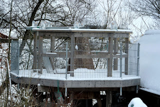
While I may have written down my observatory dimensions somewhere they had since become lost to time. So I found an early image of the bare construction and added the freshly measured dimensions for future reference. Metric on the right. Imperial on the left.

The observatory floor is 4.1m or nearly 9' from the ground. The pier about 13' high to the top plate. The large mounting adds considerably more height to ensure a horizontal view will clear the dome track.

Naming the image clearly will allow me to find it again. Almost all of my 1.3 million images are completely unindexed. Making it a very slow process to do more than scroll through Picasa. I probably don't have enough man years left to do any serious sorting of images by subject matter. So  I'll have to wait for AI to go through them at some point. Google's AI image sorting doesn't find all of those I search for. So I may have some wait before it becomes a lot better at it.


Click on any image for an enlargement.
*

21.2.18

SOLAR OBSERVATION SAFETY WARNING!

 *

 WARNING: SOLAR OBSERVATION REQUIRES GREAT CARE AND SAFE FILTRATION.
INSTANT AND PERMANENT BLINDNESS CAN EASILY RESULT FROM SIMPLE MISTAKES. NEVER LOOK AT THE SUN THROUGH ANY LENS, MIRROR OR INSTRUMENT UNLESS IT HAS BEEN FULLY TESTED AND APPROVED FOR SUCH USE. YOU FOLLOW MY EXAMPLE ENTIRELY AT YOUR OWN PERIL! THE DANGERS OF INSTANT BLINDNESS ARE VERY REAL!


In the interests of safety certain popular online forums [like CN] do not condone discussing the modification of solar telescopes nor their use. This is a highly specialized area of DIY or ATM [amateur telescope making.]

We live in a world where idiocy is rife. Litigious idiots regularly make the headlines as if their own idiocy was meant to be capitalized. Further countless idiots prove their drooling idiocy every time they go online.

Read the warnings at the top of all the pages dealing with my solar telescope modification.

Don't blame me if you are permanently blinded by your own drooling inadequacy! Even with well over 50 years of amateur telescope making experience behind me I still take every possible precaution because I am so well aware of the very real dangers. Concentrated infrared and ultraviolet can be completely invisible and still blind you instantly and permanently!

My solar telescope has a large, specially designed Baader D_ERF [heat rejection ] filter behind the objective. Many solar telescopes put the filter in front of the objective to reject heat, IR and ultraviolet before they even enter the telescope. Skilled telescope makers have discovered you can cheat to some degree on the size of the filter by placing it securely inside the instrument. The heat falling on the highly reflective filter is pushed back out of the objective.

I have used the original refractor baffles to ensure no unfiltered light can possibly sneak past my multiple, highly professional, high tech, filter defenses against instant blindness.

There follows the vital PST H-alpha etalon. Which narrows the bandwidth of the remaining light passing through the rejection filter.

Then there are two more special solar filters: The PST/Maier ITF and the PST Blocking Filter in series. These remove yet more of the heat and light intensity in the already filtered image.

All of these special solar filters are well proven and made by the top manufacturers of solar telescopes and equipment in the world. There is nothing remotely amateur about their equipment and their filters. Their very high cost ensures very high levels of quality control for user's safety. Anyone who thinks they can mix'n'match these very specialized tools, had better do some serious homework first!

The Coronado/Meade PST [Personal Solar Telescope] currently costs nearly £900 new for a modest 40mm aperture. The Baader D-ERF costs several hundred pounds to several thousand pounds depending on size. Larger solar telescopes cost from nearly £2000 to tens of thousands of pounds. The high price reflects the need for total quality control of very high tech specialized equipment always used in unison by knowledgeable users.  

Without these special filters a 6" aperture refractor lens can instantly set fire to wood or similar materials. Not only would the focused beam cause instant blindness, if you were daft enough to look into the telescope. It would probably completely destroy your eyeball, if it didn't boil or explode! IN AN INSTANT!! Consider yourself warned.  

Click on any image for an enlargement. 
*

Going H-alpha: Correcting etalon: focus error.

 *
 WARNING: SOLAR OBSERVATION REQUIRES GREAT CARE AND SAFE FILTRATION.
INSTANT AND PERMANENT BLINDNESS CAN EASILY RESULT FROM SIMPLE MISTAKES. NEVER LOOK AT THE SUN THROUGH ANY LENS, MIRROR OR INSTRUMENT UNLESS IT HAS BEEN FULLY TESTED AND APPROVED FOR SUCH USE. YOU FOLLOW MY EXAMPLE ENTIRELY AT YOUR OWN PERIL!


My first trial on the sun yesterday required I swap the correct 80mm extender for a 40mm to reach focus. This introduced a 40mm error in the PST etalon position relative to the focus of the 6" objective. The rule is to match the PST's 20cm inside focus position for the leading edge of the etalon tuning ring.

My error was in using a 2" star diagonal which has far too long an optical path length.

There seemed to be no obvious way to connect the ITF/BF filter stack to a 1.25" star diagonal. Then I remembered I had a second, no-name 1.25" star diagonal.

Unscrewing the eyepiece holder provided a female thread which exactly matched the ITF's tubular holder. The 1.25" chromed spigot fitted a 2" to 1.25" adapter.

Using the 40mm extender after the AOK etalon adapters gave me the final piece of the puzzle. The 80mm extender can go back into the plywood ring in the tailpiece of the refractor to bring the etalon to the correct position.

I now have an awful cold so testing the new layout may be slightly delayed despite the usually rare sunshine.


Despite my cold the bright sunshine meant I dragged myself outside to set up the H-alpha modified 6" refractor. It was soon obvious that neither of my 2" extenders was of the right length. I had a choice of 35mm or 80mm This gave me 97 or 102cm instead of the desired 100cm to the etalon from the objective. So now I have ordered a WO 2" x 50mm extender for the tailpiece ring. The best option was the 102cm [8cm extender] which gave me simultaneous prominences and some surface texture. In both cases the post etalon, optical path length was also badly wrong. Which is hardly surprising since it was working on the wrong angle and length of light cone.

I also climbed the stepladder to check how much of the D-ERF was fully illuminated. The bright circle of the light cone was falling over the surrounding baffle slightly. So I shall have to move the D-ERF even nearer the tailpiece. With perfect hindsight I should have bought the 110mm D-ERF despite the extra cost. That would have placed the filter more centrally instead of right down near the tail end. The brilliant spot of reflected, re-focused light from the D-ERF was sitting on the objective lens. I just hope the heat doesn't do any damage.  

UPDATE: I had ordered a 2" William Optics extender and expected it to be 50mm or 50.8mm . Which is the metric equivalent of 2".  It turns out to be 60mm long. I am awaiting a response from the dealer because there is no mention of length on their website. Nicely made and finished, though. With a compression ring and two decent thumbscrews for a firm grip on the AOK etalon adapter.

Click on any image for an enlargement. 
*

18.2.18

Going H-alpha: Connecting it all to the refractor & first H-alpha light.

 *

WARNING: SOLAR OBSERVATION REQUIRES GREAT CARE AND SAFE FILTRATION.
INSTANT PERMANENT BLINDNESS CAN EASILY RESULT FROM SIMPLE MISTAKES.
NEVER LOOK AT THE SUN THROUGH ANY LENS, MIRROR OR INSTRUMENT UNLESS IT HAS BEEN FULLY TESTED AND APPROVED FOR SUCH USE. YOU FOLLOW MY EXAMPLE ENTIRELY AT YOUR OWN PERIL!

With the D-ERF cell completed and the filter installed I just need to connect the star diagonal/etalon/filter assembly to the 6" OTA. While I could plug it straight into the 2" focuser that would push the etalon much too far out. Though I could shorten the main tube to compensate.

The cheapo 2" SCT Crayford focuser would be easy to fit to a simple plate but would struggle with the remarkable weight of the entire tailpiece filter assembly. Just over a kilo or 2.3lbs. I'd rather save my Vixen 2" Newtonian focuser for the 10" reflector when I am inspired to start working on that again. That focuser is about 10cm high when full wound in.

I was considering turning an adapter ring to replace the big Vixen 2" refractor focuser but that would need to be 110mm in diameter.  Some means of clamping the 2" nose of the front etalon adapter would then be necessary. Which would probably require very long threads for very long, radial pinch screws. That can't be done with normal hand tools. Nor do I have a stump of 110mm aluminium bar to make an adapter ring of that diameter. So I need to look at the OTA connection problem again.

A turned, birch plywood ring could plug the 6" refractor's tailpiece. The entire etalon/filter assembly could then be fitted to a 2" internal diameter adapter ring with a larger flange. The much smaller diameter of this flanged adapter would allow normal, radial pinch screws to be fitted.

It is probably unnecessary to have a focuser for the refractor because the PST etalon wants to be fixed at 20cm inside focus. The PST moved the pentaprism as its focuser and that lay between the etalon and the eyepiece filters. So the etalon to ITF/BF distance is obviously an acceptable variable, within reason.

The images show the result of turning an 18mm, 3/4" plywood adapter ring in the lathe. By carefully turning and boring the ring to size, both inside and out, I obtained a perfectly concentric, push fit exactly on axis. Because the plywood ring was turned in the chuck the surfaces are all perfectly square to each other. The 2" extension is a very firm fit with no sag or wobble.

I put a marked 120cm batten through the empty Celestron main tube first to confirm the exact position of the etalon relative to the 6" f/8 objective's focal plane. I just happened to have a 2" extension of exactly the correct length with a brass compression ring to avoid damaging the AOK etalon : 2" adapter. The 2" extension allows easy removal of the etalon/filter assembly for storage. It takes only a few seconds to release the components for use on other instruments.

Now I just need to fit the D-ERF in the correct position in the main tube and screw the tailpiece back on. Job done. I should now be able to observe the sun in H-alpha with a 120mm clear aperture. There is a risk of some sunshine tomorrow!


And sunshine there is! I've been too busy this morning to make a start and still need to drag the heavy mounting and its massive pier across the snow.

Success! I had to use a shorter 2" extender to reach focus. Then I tuned the etalon to reach an overall 'orange peel' with a few small prominences in the same view. The Cemax 12mm eyepiece offers about half a solar diameter in field of view. I tried a 26mm Plossl but that didn't help. It needed my eye to be held well back to get the full field of view. Back to the Cemax.

The sun's image is huge @100x but razor sharp on the limb. No sign of any spots so far but several prominences including an arch. The sun is regularly obscured by cloud and only 23° above the horizon. Going back out to try and capture some snaps with my short zoom, Canon P&S digital camera. Not sure how well that will work on a 12mm EP. Back soon.

It wasn't to be. After the sheer luck of earlier sunshine it has become heavily overcast. This was the best of only a few handheld snaps. Later the sky finally cleared to coincide with the sun dropping below the ridge of the house. I managed to snap one prominence but the contrast is far too wide for the camera to manage successfully. Unretouched image except for resize. Centering the camera lens on the 12mm Cemax is hard work.

Click on any image for an enlargement.

*

16.2.18

Going H-alpha: ITF/BF stack/eyepiece holder adapter.

*
WARNING: SOLAR OBSERVATION REQUIRES GREAT CARE AND SAFE FILTRATION.
INSTANT PERMANENT BLINDNESS CAN EASILY RESULT FROM SIMPLE MISTAKES.
NEVER LOOK AT THE SUN THROUGH ANY LENS, MIRROR OR INSTRUMENT UNLESS IT HAS BEEN FULLY TESTED AND APPROVED FOR SUCH USE. YOU FOLLOW MY EXAMPLE ENTIRELY AT YOUR OWN PERIL!
 
 
I have had a look at the PST's ITF and Blocking filter components. These two could easily be fitted into a bored out 2" to 1.25" eyepiece adapter. A cheapo, plain one will do. No need for a brass compression ring. Though one could easily be incorporated into a larger diameter slot cut in the adapter's newly increased bore.

It won't take much time to bore out the adapter to increase the usual 31.8mm EP size to the 36mm Ø of the PST's ITF/BF5 tubular section. The adapter's usual pinch screw will provide a lock on quite a useful sliding fit.

The Blocking filter [with EP holder] from the PST will screw onto its original thread on the ITF to make the standard PST filter stack.

Which cannot escape from its adapter thanks to the shoulders at each end. While providing nearly 1/2" of [focusing] travel if required. More, if the adapter is counter-bored to clear the shoulders.

After cleaning the threads on the ITF/BF I was able to screw them back together after slipping them both into the bored out [now] 50mm : 36mm adapter. Turps substitute worked as well on the gummed up threads as it did as a cutting fluid on the lathe. It is quite magical how well turps works on aluminium being turned in the lathe.

The problem with this 2" adapter idea is that it demands a 2" star diagonal and I'm not sure it should be necessary given the modest diameter of the PST's filter elements. The complete 'plug-in' set-up is shown in the image right. The Etalon to EP distance of 20cm is also achieved. Though 2" extenders are readily available if they were needed. Or the long and sturdy AOK female adapter could be slightly shortened if need be.

Since it is so reflective, it is quite hard to judge where the mirror surface lies inside the 2" star diagonal. So measuring the exact, optical path is prone to personal error. I don't have a calibrated feather to avoid damaging the delicate coating.

Silly me! I just need to lightly pencil crossing lines centered on both 2" spigots. The reflection point [at the mirror surface] is then indicated by the corner of the square formed by these pencil lines and the diagonal's own body casting. So I can now confirm that the optical path length from the far side of the etalon to the lower rim of the eyepiece is close to 20cm when the [now sliding] ITF/BF filter stack is pushed right down.

The focal plane [at the field stop] of the Cemax 12mm  EP lies deep inside its chromed barrel.  25mm from the bottom rim, in fact, from examining a pencil using the EP as a magnifying glass. This almost coincides with the lower edge of the gold band plus about 5-6mm, or so.

I wonder whether I need to compensate for this small difference in the 20 cm measurement? The answer is probably to see where the system focuses when connected to the refractor and go on from there. I can counter-bore the top of the already bored out adapter to reduce the optical path length, if needed, by sinking the top [BF] shoulder. Making the path length longer is very much easier. I just lift the filter stack and re-tighten the pinch screw.


Click on any image for an enlargement.
*

15.2.18

Going H-alpha: Replacement ITF from Maier.

*


WARNING: SOLAR OBSERVATION REQUIRES GREAT CARE AND SAFE FILTRATION.
INSTANT PERMANENT BLINDNESS CAN EASILY RESULT FROM SIMPLE MISTAKES.
NEVER LOOK AT THE SUN THROUGH ANY LENS, MIRROR OR INSTRUMENT UNLESS IT HAS BEEN FULLY TESTED AND APPROVED FOR SUCH USE. YOU FOLLOW MY EXAMPLE ENTIRELY AT YOUR OWN PERIL!

Whoopee! My Maier ITF replacement arrived in the post. Excellent service from Both Maier and the international postal services. It came with an O-ring which was not part of the Coronado ITF construction.

I have sought advice on whether to fit the O-ring first or the filter. I know the shiny green side of the filter points towards the objective/sun. With the deep red towards the eyepiece. The O-ring has me stumped. I have no useful data to make a valid choice for its position.

The images here show the new filter in the PST housing.  Only the glass filter is supplied by Maier.

I'm thinking of putting the O-ring in first to help to seal the exposed filter face and to push it further out of harm's way. Looking at it logically, as a regular PST spare part, it would be better protected inside the black casing. But still subject to changing atmospheric humidity. While the red, backside, of the filter is much better sealed inside the ITF/BF tubular housings.

Maier tell me that the filter surfaces are fragile and that I should only handle it by the edges. Which I duly did after having removed the screw-in filter housing and its locking ring. I used a small pair of engineer's, screw-adjusting dividers without any effort. No thread locking medium thank goodness!

Had I known what to do with the O-ring it would have been no more than a 5 minute job. Provided of course I had previously separated both filter housings from the PST.  ITF replacement can still be done provided the pentaprism has been removed from the black PST housing. I'm not sure it is possible with the prism simply backed as far away as it will go via the focusing knob.

The clarity of view through the Maier filter is truly remarkable compared with the almost opaque [rusty] Coronado original. I can see the darkened room quite clearly and read newsprint easily through the Maier ITF. The view is cast in deep red with only a table lamp for lighting.

The view through the new Maier ITF filter on an overcast day with snow on the ground:

Via the original Coronado ITF it is so dark that I can barely make out anything at all. The [white] computer screen is almost invisible at 2' and the lit lampshade, at a similar distance, only dim. This is not a function of the colour density of the old and rusty filter. It is quite simply, almost opaque. It seems sensible to replace an old ITF filter if it shows a rusty complexion despite immaculate outer coatings. Otherwise, you won't know what you're missing.

*

14.2.18

Going H-alpha: The AOK PST etalon : 2" adapters have arrived.

*

WARNING: SOLAR OBSERVATION REQUIRES GREAT CARE AND SAFE FILTRATION.
INSTANT PERMANENT BLINDNESS CAN EASILY RESULT FROM SIMPLE MISTAKES.
NEVER LOOK AT THE SUN THROUGH ANY LENS, MIRROR OR INSTRUMENT UNLESS IT HAS BEEN FULLY TESTED AND APPROVED FOR SUCH USE. YOU FOLLOW MY EXAMPLE ENTIRELY AT YOUR OWN PERIL!

Excellent service from Beat Kohler @ AOKSwiss in the swift arrival of my PST etalon to 2" adapters. 

All images are taken in sunshine and flash to bring out the maximum detail. The items look much blacker to the naked eye and even more matt inside. 

The PST etalon's [female thread] rear adapter feels much heavier and very sturdy. It has a knife edge baffle. Two thumbscrews are supplied for 2" fitting eyepieces, star diagonals or 2" to 1.25" adapters.

Meanwhile the front adapter feels very light indeed and also has a knife-edge baffle. 

The machining is crisp, evenly blackened and threads onto other components very smoothly. They do feel like good quality workmanship without that high gloss black finish most accessory makers choose. I find the matt black purposeful and sophisticated.

Note the long internal thread for fitting 48mm filters in the front [male thread] adapter. This will also reduce scattered or grazing light. 

The lower right image shows both adapters screwed [partially] onto the PST etalon in the middle. Sunny side of the Etalon faces left. 2" star diagonal inserted for scale.

I have yet to attack the "Loctite" residue on the PST's etalon threads. So don't want to damage the threads on the new adapters. It sounds [from online homework] as if most normal solvents will soften the hardened glue residue and allow a brass brush to clean off the rest. 

It seems too obvious to point out that the solvent must NOT be allowed to get near any optical components. So a lightly dampened cloth is more sensible than sloshing liquid solvent all over the place. Working outdoors, or in a well ventilated situation, is considered essential to good health practice.


Click on any image for an enlargement.
*

13.2.18

Going H-alpha: Building a D-ERF cell.

*

WARNING: SOLAR OBSERVATION REQUIRES GREAT CARE AND SAFE FILTRATION.
INSTANT PERMANENT BLINDNESS CAN EASILY RESULT FROM SIMPLE MISTAKES.
NEVER LOOK AT THE SUN THROUGH ANY LENS, MIRROR OR INSTRUMENT UNLESS IT HAS BEEN FULLY TESTED AND APPROVED FOR SUCH USE. YOU FOLLOW MY EXAMPLE ENTIRELY AT YOUR OWN PERIL!

A trip to a charity shop produced this potential filter cell: 

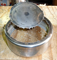
A label, sticky tape and postage stamp, wet sponge holder from yesteryear. I have removed the non-slip rubber cup base and sponge. 100mm Ø x 35mm deep in 1mm thick stainless steel. The front hole is 89 mm Ø.

The water hardness is still clinging from years of use. This will easily rub off to leave a pristine, brushed finish. Now I just need to find a way to get the 90mm Ø, glass, filter disk safely inside it.

The images right show the process from freehand, chain-drilling the base inside the scribed circle. To removing the 'tin lid.' To the completed ring cleanly turned on both sides to 88mm and 93mm Ø holes.

Extreme care must be taken not to have such a flimsy item snatched out of the chuck on the lathe. I filed the rough hole smooth after the chain drilling before risking the piece in the lathe. Then used extremely fine power feed with small depth of cut increments.

The greater depth and larger diameter [compared with the earlier lid] will allow space for cork packing pieces. Plus the deeper cylinder sides will allow radial screws to hold the completed filter holder in the main tube of the 6" refactor. All without risking damage to the filter itself. The gods of creativity do sometimes smile upon the ATMer.

The enlarged hole will allow for later, easy glass insertion. The new and smaller hole will leave a better safety lip to retain the glass disk against small cork pads, glued in place.

The perimeter of the glass disk will sit between thicker cork pads to allow for differential, thermal expansion. It is vital that the filter is fully relaxed in its cell without any strain or distortion. Slight tilting is usually vital to avoid multiple reflections of the solar image.

I must also consider cell assembly and positioning. Without risking the perfect optical surfaces with their multiple optical coatings. The safest way to fit glass in a cell is to lower the cell onto the glass. While the glass itself is resting on a tissue protected object like an inverted drinking glass. This is the safe way to remove and refit objectives in their cells without the risk of tipping and jamming. Providing, of course, patience and care is taken.

Later it occurred to me that the filter glass can be placed at the back of the cell on thin, cork pads. This would allow the radial fixing screws [to the main tube] to easily clear the glass. The screws would be nearer central in the cylindrical walls of the cell for better symmetry. The clear open front of the cell will allow easier insertion into the main tube. With the front rim offering a secure finger-hold during fitting and possible removal.

In the end I had simplicity thrust upon me. No need for radial fixing screws nor spacers. The nearest original baffle of the Celestron 6" was almost the same aperture as the energy rejection filter. So I simply drilled and bolted them together. The whole unit will slide the 50cm down the main tube away from the objective. Then can be turned square to the tube to jam it in place.

Job done apart from the cork pads and lining to protect and support the filter glass. CSK screws would have been more sensible but I had nothing in the small size I needed. I can make up the difference in head clearance with more cork. Or just buy some countersunk screws.

I used a steel rule and scalpel to cut two 30mm wide strips from 2mm cork sheet. Then two more strips only 12mm wide. The two wider bands were sprung into the housing after cutting to exact length. Then removed and glued together with white wood glue while in place in the cell. Thanks to the shoulders on the filter housing there was no need to glue the cork to the metal.

I then glued one of the narrower strips flush with the back of the doubled bands. Now I need to decide how to safely hold the filter in its snug cork bed. I have the cork strip ready but can't glue it if I ever want to remove the filter again. Short, radial screws and nuts holding the second cork strip? This seems a bit crude for my tastes. I'll think about it overnight.

 Now I'm thinking about a narrow but thick strip of vinyl or leather to retain the filter glass. Small Csk. screws at 120° should hold it firmly if the strip is stiff enough. So it's back to the charity/thrift shops looking for a thin belt or strap to act as donor material.

The last two images show the 90mm D-ERF mounted in its cell. The cork offers mechanical protection to the filter glass. With the baffle facing the sun, the arrow on the edge of the filter is pointed correctly. The clear aperture is about 88mm and the lining materials will be blocked from heating effects by the baffle. It will be inserted from the focuser end of the main tube since it will be much nearer that end than the objective end. The low angle reflection from the sun/objective side is purple. More a bluish reflection from the focuser side.

Click on any image for an enlargement. 
*

Going H-alpha. The Baader D-ERF heat rejection filter.

 *

WARNING: SOLAR OBSERVATION REQUIRES GREAT CARE AND SAFE FILTRATION.
INSTANT PERMANENT BLINDNESS CAN EASILY RESULT FROM SIMPLE MISTAKES.
NEVER LOOK AT THE SUN THROUGH ANY LENS, MIRROR OR INSTRUMENT UNLESS IT HAS BEEN FULLY TESTED AND APPROVED FOR SUCH USE. YOU FOLLOW MY EXAMPLE ENTIRELY AT YOUR OWN PERIL!

I spent the morning preparing a 10mm thick ring for my 90mm D-ERF [Energy Rejection Filter] expecting it to be 8mm thick. Baader's own website says 6mm glass. Now it has arrived it clearly says 5mm on the box and is confirmed with vernier calipers. Should I ask Baader for a 1/6 discount? Later, I was able to confirm that 5mm is normal thickness for the 90mm D-ERF thanks to a resident optical expert on Stargazer's Lounge.

Superbly packed in a neat box, bubble wrapped bag inside a lip sealed, polythene bag and then lens tissue. 

The D-ERF filter shows very different reflections and transmission colours with changing light and angles of viewing. Upper image with flash. Lower image natural north facing daylight with computer screen behind.

I can now seek a suitable [household] object to house the expensive heat rejection filter. I do have a rather nice, stainless steel lid which is 92mm internal diameter but only 10mm deep. I would prefer something deeper to make room for radial fixing screws as well as the glass itself. Then there is the cork padding to allow for.

Cutting out the base to [say] 88mm Ø would be quite hard work in
stainless steel. Aluminium is a very much nicer [and softer] material to work with. Though stainless steel lasts forever out of doors.

Chain drilling is a quick way to make a large hole in metal. Which can then be turned smooth in the lathe once the circle has been broken or sawed out. Or one can evenly file the hole smooth if one doesn't own a lathe.

I would prefer metal for this task because the heat of the sun is fiercely concentrated by the large objective. More so, because the filter [and its holder] will be placed halfway down the main tube. So plastic or wood must be deleted from the list of possible building materials.


Click on any image for an enlargement. 
*

10.2.18

Going H-alpha: Removing the Etalon from the PST body.

*

WARNING: SOLAR OBSERVATION REQUIRES GREAT CARE AND SAFE FILTRATION.
INSTANT PERMANENT BLINDNESS CAN EASILY RESULT FROM SIMPLE MISTAKES.
NEVER LOOK AT THE SUN THROUGH ANY LENS, MIRROR OR INSTRUMENT UNLESS IT HAS BEEN FULLY TESTED AND APPROVED FOR SUCH USE. YOU FOLLOW MY EXAMPLE ENTIRELY AT YOUR OWN PERIL!

You would not believe the struggle I had to break the thread locking compound on the Etalon! It took an hour just to get the first, audible "crack." Even then it took a lot of force to keep it unscrewing. I was afraid the housing would break where it is slotted for the tuning. Or that the Boa's rubber strap would break because it was taking such a beating!

I added a length of PVC plumbing pipe to contain the rubber strap and provide a more comfortable handle. [See image right]  It also provided a little more leverage. The Boa strap is asymmetric to the handle. Which meant the Boa's body was hitting the PST's metal housing every time I tried to put some serious effort into it. It took two, well tightened, Bessey F-clamps just to hold the body still on the bench! I was very careful not to hit the sun finder prism in the corner of the casing.

Thankfully I had done my online homework and knew about the long, fine screw hidden under the concealing paper label beneath the knurled 'rubber band.'

The rubber band needs a fine screwdriver to lift it enough to start pushing it off sideways. Try not to scratch the finish. A cocktail stick might be a better tool.

If I hadn't removed the tuning screw it would have been forced against the internal tuning mechanism and bent.  Making it impossible to remove. The thin, rubber band sits on a thin metal sleeve. All these parts must be removed before the BOA strap wrench can possibly be used. I also removed the two narrow O-rings around the etalon body to save damaging them with the Boa. These O-rings provide smooth friction and even support for the tuning band.


Click on any image for an enlargement. 
*

Going H-alpha: Links to PST modification sources and videos:

 *

WARNING: SOLAR OBSERVATION REQUIRES GREAT CARE AND SAFE FILTRATION.
INSTANT PERMANENT BLINDNESS CAN EASILY RESULT FROM SIMPLE MISTAKES.
NEVER LOOK AT THE SUN THROUGH ANY LENS, MIRROR OR INSTRUMENT UNLESS IT HAS BEEN FULLY TESTED AND APPROVED FOR SUCH USE. YOU FOLLOW MY EXAMPLE ENTIRELY AT YOUR OWN PERIL!

I am indebted to all the solar enthusiasts who have shared their modifications to their PSTs and well beyond.

In no particular order:

PST MODIFICATION

Equipment-on-site [Astronomy Center Todmorden]

Solar Equipment - Pieter Vandevelde

Modification of a Coronado PST. PDF  [Matthius Bopp]

Diane's Mod My PST Page

Lunette 230mm   Brahic huge iStar Solar telescope build in French.[Use Google Translate.]

Viewing With Solar Telescopes: Mikes PST Mods , 150mm Istar , !00mm Skywatcher and Original Celestron 102 XLT

http://www.iseefar.nl/pstmod%20eng.htm

https://youtu.be/ubj-eWYyzUY

https://youtu.be/YyHOMaiwJzA

https://youtu.be/Gd45A1Dwwl4

https://youtu.be/aBjfyM3o1VE

https://youtu.be/zknsRONtUhw

https://youtu.be/bWtRufuSkLY

There are many others if you search online. Some sites are files which do not seem to suit normal links even when saved to Bookmarks.

SolarChat! - Solarchat! Forum Index

A specialist solar forum where solar construction projects can be freely discussed.  
 
Stargazer's Lounge forums have excellent and ongoing, reference material on PST modification and solar telescope building. With active solar sections, Instrumental and DIY astronomy forums which can be subject searched. Experienced, resident experts are always on hand to offer useful advice from years of real, hands on practice.

Cloudy Nights forums has a very strict policy that no modified solar telescopes be discussed or their imaging results posted on CN forums. There is no obvious warning notice on the solar forum but you will be boorishly reprimanded if you do post modifications. Or even post images taken with your modification projects.

*

8.2.18

Going H-alpha: Celestron 150mm OTA mods.

*

WARNING: SOLAR OBSERVATION REQUIRES GREAT CARE AND SAFE FILTRATION.
INSTANT PERMANENT BLINDNESS CAN EASILY RESULT FROM SIMPLE MISTAKES.
NEVER LOOK AT THE SUN THROUGH ANY LENS, MIRROR OR INSTRUMENT UNLESS IT HAS BEEN FULLY TESTED AND APPROVED FOR SUCH USE. YOU FOLLOW MY EXAMPLE ENTIRELY AT YOUR OWN PERIL!

This morning I put my old Celestron up on the Fullerscope's MkIV mounting to check focal distance behind the OTA. The mounting saved me messing about with props while trying not to drop the OTA. I just had to align the sun's image on a piece of dark sandpaper then measure back to the tailpiece adapter with a steel rule.

The previous owner of the Celestron was an imager. He had already shortened the main tube of the 6" refractor and fitted a Vixen 2" focuser. I found I could not get focus until I added long extension tubes and/or a star diagonal. [See old image right.]

It seems I have 26cm from the back of the focuser adapter casting to the focal plane. Which would allow adequate clearance for the tuning ring if the PST is added straight onto the tail end without its objective. So no main tube cutting is required to achieve the 20cm inside focus requirement for the Etalon.

Now I need to provide a 10cm, 4" long adapter to the OTA which will screw into the female, etalon thread at the other end. The extra length [over 6cm] will be required to attach the tubular adapter to the refractor. I shall turn an adapter ring to replace the Vixen, 2" focuser. 


As already discussed the plan is to use an internal 90mm Baader D-ERF to reflect the sun's heat away. This will be fitted some distance from the objective, inside the OTA. It also doubles duty as a UV/IR rejection filter.

I imagine a 10mm thick aluminium ring, with spacers at 120° around the rim, will allow much easier handling within the confines of the main tube. Compared with a solid, closely fitting ring, it will also be easier to align radial, fixing screws.

Now I have finally decided to discard the PST's main housing I shall have to arrange the filters at a suitable distance from the etalon. Then add a star diagonal to bring the eyepiece to a comfortable viewing angle. Star diagonals have the advantage of using up more of the focal length than straight tubes. The ITF and BF5 Blocking filter, tubular fittings can go on the eyepiece end of the 2" star diagonal just as they do in the PST.

All this will make for a rather long and unwieldy tubular structure projecting from the tail end of the 150mm refractor. Though there is really no need to use 2" astro fittings at considerable expense and possible flexure. I can use larger diameter aluminium tubing with turned inner rings to support vital components at the correct distance.


I have now ordered the PST Etalon to 2" adapter set from Beat Kohler of AOKSwiss. Real images to follow on arrival.

http://www.aokswiss.ch/d/zub/adapter/50.8-pst.html

 http://www.aokswiss.ch/d/zub/adapter/pst-2''.html

AOKswiss online - deutsch

Use Google Translate. I found an English version of Beat's website by accident but can't find my way back again. I could have been using Google Translate in Firefox and produced a false memory.


Click on any image for an enlargement.
 
*

Going H-alpha: PST dismantling: Images of parts.

*

WARNING: SOLAR OBSERVATION REQUIRES GREAT CARE AND SAFE FILTRATION.
INSTANT PERMANENT BLINDNESS CAN EASILY RESULT FROM SIMPLE MISTAKES.
NEVER LOOK AT THE SUN THROUGH ANY LENS, MIRROR OR INSTRUMENT UNLESS IT HAS BEEN FULLY TESTED AND APPROVED FOR SUCH USE. YOU FOLLOW MY EXAMPLE ENTIRELY AT YOUR OWN PERIL!

As a service to those contemplating dismantling or diagnosing their PST I offer a series of images.  Click on any of them for  a larger image.

 The various parts of the dismantled PST.
The Etalon optical group is still in place.
 The two eyepiece holder components with ITF [Left] and BF5 Blocking filter.[Right]
The ITF and 5mm Blocking filter inverted. The BF5 is actually a thick block of glass. Larger blocking filters are available, built into special solar diagonal housings, at hugely increased prices.
The inside of the poorly blackened 'gold' tube. Looking towards the PST's objective. One wonders whether simple baffling would have improved the view? Perhaps they were worried about overheating the internal components? The later [blue coated] objectives had no filtering. So the focused [concentrated] heat of the sun would fall on any intermediate baffle when the PST was not perfectly aligned on the sun.


The threads at the etalon end of the gold tube. No idea why they cut the large internal thread. Nothing screws in here on present PSTs. The external thread fits into the etalon housing/tuning assembly. Note locking compound residues on the external thread. Online discussion suggest using various solvents and a wire brush. A [dry] normal toothbrush has no effect on the hardened residue.


The main focusing pentaprism shortens the instrument to make it more compact. Focusing is achieved by sliding the prism diagonally using the two studs in a groove in the housing for alignment. There is nothing intrinsically wrong with the system but it is poorly configured. With screw access via the covering plate provided to straighten the often twisted prism locked inside the housing.


The focuser threaded rod runs in the prism block against spring compression.


The etalon group from the 'outside' of the PST housing. Normally hidden by the gold tube and 40mm objective. The etalon looks quite clear to the naked eye with only a slightly blue cast.


Etalon from inside the housing. A negative and positive lens ensure parallel light passes through the etalon in the middle. It is the power of these lenses which demands a 20cm etalon position inside the focus of an f/10 objective. A 'shorter' or 'faster' focal ratio will stop down the objective to f/10.


ITF unscrewed from its tubular housing using a large pair of dividers. There is no obvious 'Locktight' compound but possibly a thin, rubbery thread locking agent to keep the ITF in place. The mirrored, blue coated side faces the objective. The red side towards the eyepiece.
ITF unscrewed inside view. The matching thread to the BF5 is again loaded with Loctite residue. Which had made dismantling the PST a major headache. Meade claim 'no user adjustable parts inside.' One can understand their wariness to just leaving the threads unlocked. The world is full of drooling idiots who would quickly blind themselves. Then chase after an ambulance chaser to help to compensate them for the own drooling idiocy. It's a sort of reverse Darwin effect. The drooling idiots survive to breed. When they would otherwise, quickly make themselves unable to do anything useful with their lives.


The ITF filter with solar illumination and the camera on macro to focus on the filter itself. The 'rust' trapped between the elements is clearly visible despite both surface looking pristine and coated. The ITF consists of two elements. The Maier [USA] replacement filter is claimed to be better sealed at the edges to avoid moisture ingress. Its relatively modest cost in the US will be considerably inflated by European taxes.


Click on any image for an enlargement.