29.9.16

2" shaft mounting Pt.40: PA/Dec Overhang.

 *

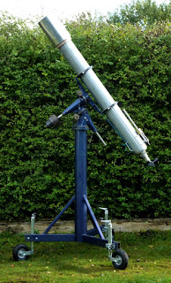
The large overhang beyond the top PA bearing was irritating me if I kept the RA wormwheel on top. A preference for this position required further thought.

The "painted" image [right] shows what happens if the wormwheel boss is removed. The boss provides a three point, adjustable, radial, nylon "clutch" to allow telescope movement independent of the wormwheel. As I already have a clutch in the form of a PTFE disk pressing down from just above the wormwheel the boss becomes irrelevant.

Its removal saves a useful 25mm [1"] of overhang. Sadly, its absence makes very little difference visually to the degree of cantilevering. So, I might as well just leave the boss in place. Or give up trying to place the wormwheel at the axes junction. Or, just ignore the overhang problem altogether. If only I could. As an obsessive mounting admirer, of over half a century, the overhang glares right back at me. Though a fork mounting would instantly introduce yards of overhang. Without anybody giving it a second thought. It's, really, all about appearance.

The Tollok bush's un-expanded sleeve diameter is 65mm so the wormwheel won't fit on that even if I spent hours and turned away a large section of the cylinder. The Tollok bush could be slightly shortened but not enough to make it worthwhile before the opposing cones risked losing their gripping power. Best not to go there. Though Tollok do make much shorter bushes I chose the one most likely to offer maximum support to the cylinder and Declination axis.

An alternative would be to add rollers for the cylinder to run on. Not easily achieved with the large wormwheel getting in the way of any natural upward extension from the existing polar housing. Using rather large rollers might do it. They would avoid an ugly, dog-leg support system for the rollers and simultaneously reduce friction.

I have tried adding counterweight to the bottom of extended PA shafts. This doesn't work well with the former plain bearing mountings on which I have done this. The problem of increased friction is very unlikely to arise with these huge flange bearings. Their load capacity greatly exceeds anything I could possibly imagine hanging on the end of 50mm [2"] mounting shafts. Perhaps if I bought a much longer PA shaft it would completely alter the visual scale? That would mean finding the materials for another, much longer, PA bearing housing. I have thought of borrowing the longer Dec shaft and bearing housing for the PA but discarded the idea. The shorter housing looked rather lost on top of the much taller PA housing. I'd also have serious problems adding enough counterweights to a short shaft.

As I have already discussed, the wormwheel might be difficult to house right at the bottom of the PA shaft. My 55° North situation leaves little room under this steep polar angle for an 11.5" disk. I'd also need a retaining collar to stop the wormwheel from literally falling off the end of the PA shaft. That aside I lose the greatly increased stability offered to the RA wormwheel by the cylinder and PTFE 'clutch' disk. There is also the matter of greatly increased complexity in arranging a slow motion control shaft back at the eyepiece for a "bottom dwelling" worm and wormwheel. A top mounted worm needs only a straight shaft provided the worm is placed on the side of the wheel.


Click on any image for an enlargement.
*

2" shaft mounting Pt.39: How not to drop a 200+lb mounting.

*


Since the complete mounting is now so heavy I spent some time researching cranes, lifts and hoists. A cheap boat winch was attractive on price but a foolish idea for lifting such heavy loads. Let the handle go and it whizzes backwards and is very likely to cause an injury. While the much safer auto-braked, boat/trailer winch cost at least 6 times as a much and are probably still made cheaply in China. £200+ or $260+ is a very expensive toy for most of its life going completely unused! Another problem was the need for a minimum load on the winch. A winch also has to be held down somehow and anchors do not grow on trees..

It has already occurred to me to use a normal boat winch to move the present MkIV pier slowly and much more safely across the garden. Pulling it low down would avoid some of the tipping action of manual pier movement. I'm far too old to level the entire area where I observe as it would need lorry loads of gravel and sand to remove the slope and compaction. Plus lots of concrete slabs just to make it any more useful than it already isn't. 

Ratchet lifts and hydraulic [vehicle engine] cranes have their uses but not for the considerable lift I needed. More importantly I needed one which could be moved at random all around the garden. Finally, I decided to order a cheap, 1 ton capacity, chain hoist with 3m [10'] lift height. This will provide the clear lift I  need to place the [very likely] 200+lb mounting on top of what is likely to be rather a tall pier. If I ever get that far!

I shall have to provide a solid tripod or pyramidal support stand for the hoist. A four sided pyramid of 2x4s or even 3x4s [50x100 or 75x100mm] ] sounds like the most practical and sensible base for out of doors. The legs can be easily stored in loose lengths up in the shed roof out of the way. I can even hang the hoist from the ceiling joists to lift the heavy, bulky and very awkward mounting onto the bench to work on it inside the shed. Reviews of some of these chain hoists suggest some examples leave the Chinese factory full of casting sand and swarf. This sounds just like my cheapo pillar drill. I had to buy new bearings for it from brand new because of the filth and instant damage hidden out of sight. Others have been rather more lucky and they really like their chain hoists. Recognizing one "maker" from another only adds to the confusion over which to purchase. 

The Sheppach 1Ton CB01 chain hoist arrived the next day. Though made in China the quality seems fine. It worked right out of the box after I put a multiple loop of rope over one of the shed's [triangular reinforced] ceiling joists. Lifting the entire mount was completely effortless if rather noisy and quite slow over longer lifts. The noise was exacerbated by the shed's entirely wooden construction and plywood floor. The control over the height of the hook [or rather the load] is excellent. I was able to thread the PA axis shaft down through the wormwheel and flange bearings without any problem as I lowered the declination and PA shaft into the PA housing resting on the floor. Having decades of experience with indoor, electric, workshop cranes running on overhead beams I rather like the simplicity of the chain hoist for home use. 

I think I shall look out for some short webbing slings. They are far more convenient than multiple loops of rope for securing loads safely for lifting. A pair of work gloves is also a good idea as handling the chain quickly makes ones hands rather grubby. I ran the chain through a rag but it didn't help all that much with all the nooks and crannies of the chain links. One wouldn't want to wear one's best clothing while operating the hoist. At least the chains are plated rather than bare steel with all the long term problems of rust and staining hands and clothes that involves. Protective [c]overalls and industrial safety shoes/boots are the obvious choice when lifting and working with such heavy loads anyway.


Click on any image for an enlargement. 
*

28.9.16

2" shaft mounting Pt.38: Joining the axes II

*

Here I have added four long threaded rods. [studs or all threads] I drilled and tapped M8  threads for over an inch [25mm] into the top cylinder face. Stainless steel studs are screwed into the tapped holes and then pass through the two opposing plates and are held by yet more furniture nuts.

These extra studs provide an added compression effect across the declination axis bearing housing while tying directly into the cylinder. Previously I relied on the Tollok bush for Dec housing retention. It all helps to hold the 10mm [3/8"] plated box together. I fitted pairs of locked nuts to each stud to aid torquing the studs deep into the cylinder. I don't have an M8 plug tap so had to rely on a 2nd tap. This leaves a tapered thread in the very bottom of the hole. Which helps to lock the studs safely in place.

My desire to add these four 8mm [5/16"] studs to join the cylinder to the opposite plate proved extremely frustrating. I don't have a 10.5mm or 11mm drill and half the furniture nuts were slightly oversized in the shank! I wasted much of the day struggling to insert the nuts and then finding they would not turn if they did go in because of the friction. In the end I used a tapered broach to open the holes from both sides of each plate but it involved a lot of dismantling to be able to reach them all. Both sides of 14 holes on two plates is 56 broaching operations. I could have turned the nut shanks down in the lathe but that would thin their already slender walls. These things rely on thread depth rather than radial strength. Somebody somewhere decided to make them oversized. Or, more likely, they simply couldn't be bothered to check what was leaving the factory. 

Having reached this far [image left] I was still struggling to get the nuts into the undersized holes. With any of the 10 studs in place it was then impossible to fit the narrower housing plates. Much loosening and broaching later it all finally fitted together.

Removing the Tollok bush, cylinder and shaft [several times] was quite a fiddle until I removed the opposite plate to gain access with an extension hex key and ratchet.

The image [right] shows the declination housing properly assembled onto the shaft, Tollok bush and 7" cylinder for the first time. The scribbles are to remind me to allow clearance for all the obstructions including the 50mm [2"] shaft and large studs. I now have 4 x M16 studs, 14 x M8 studs, 10 x M8 screws for the the Tollok bush and four grub screws on the bearing shafts to hold it all together.

Finding room while [deliberately] just clearing all the other studs was a bit of a fiddle. I'm afraid I tend to make up my ATM builds as I go along rather than having any particular master plan. The plates still need some fine adjustment to even them up but by now it was threatening to rain.

I should now add at least four cross studs to hold the side plates firmly together. Which I duly did. Then found I was several nuts short of a set. You would not believe how many names there are for these furniture nuts. Top nuts, cap nuts, ferrule nuts, joint connectors, sleeve nuts, barrel nuts & flange nuts are but a few of them in English.  There are at least four names in Danish of a similar nature. Searching for stockists of these larger M8 [5/16"] is an absolute nightmare!

I do wish wholesalers would make it absolutely clear as to their intended purpose in life. Having to look through their terms and conditions of sale just to see if they will deal with a private customer is a complete and utter waste of  a serious browser's time and patience! Who produces wholesaler's websites! Complete morons? 


Click on any image for an enlargement. 
*
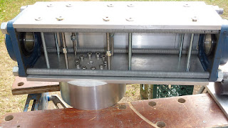
27.9.16

2" shaft mounting Pt.37: Joining the axes I

*

 The Tollok clamping bush screwed fast to the declination axis plate. Access for tightening and removal of the bush requires the removal of one of the declination housing plates. Most easily achieved by removing one of the narrower plates. This saves having to remove the 6 screws which clamp the housing together. Merely slackening off the furniture nuts and the nuts on the large studs will allow one of the narrow plates to be slipped free.


The 7" cylinder fits snugly over the Tollok bush. This leaves the grub screws on the flange bearing just accessible. Removing the heavy shafts seriously reduces the weight of the bearing housings but takes time and requires loose studs.

[Left] Note the "spy" hole to confirm the shaft is fully home in the Tollok bush. Once the bearing housing is fitted together it is impossible to see the end of the shaft.

This image [Right] shows the inside of the bearing housing plate after I have fitted six 8mm [5/16"] studs to help to hold the bearing housing together. I have yet to fit any through studs to hold the cylinder firmly to the opposite plate of the bearing housing.

The mounting all but assembled except for the wormwheels, worms and supporting base. 

The weight is now well beyond my capacity to lift the entire mount.


The mounting broken down into fairly manageable parts.

The long declination shaft is quite a lift in itself.

I shall have to weigh all the components to see how heavy the mounting is at this stage.


                                    Lbs   
Dec Hse + PA shaft.....62.3   
Bare dec shaft.............28.2
PA hse.........................28.2
Saddle...........................3.5
RA wm-wheel...............8.6
Worms + bush..............6.0
Dec wm-wheel.............5.2
2 x worm plates............5.0
                                   ___      
Total.........................147.0


Click on any image for an enlargement.
*


26.9.16

2" shaft mounting Pt.36: Holding it all together.

*
I was struggling with ideas for an attractive and efficient means of holding the axis housings together. Then I found some oversized 8mm [5/16"] hex socket furniture nuts at a DIY superstore. Some 8mm studding [all thread] provided the means to join opposing sides.

Marking suitable points to site the threaded rods suggested a position to pass close to the main studs. The smaller studs would then be denied the ability to move sideways if the housing plates should manage to slide. Not that it would be likely with lengthways compression applied by the large studs. The smaller studs sandwich the side plates between the wider ones. Great care must be taken if I should decide to add more smaller studs at intervals to increase the clamping pressure. Clear room must be left for the large cylinder. Any bolts or studs to hold the housing to the cylinder must be over 6" long.

Each new fixing will increase lateral resistance to plate movement by improving the clamping pressure. Note the scale of the heavy 2" axis shaft and the large and smaller studs in the internal image above.

The images show the general idea. With earlier images taken without side plates to show the "innards."

The final image [left] shows the declination axis standing on end with the side plates firmly clamped in place. Endways movement of all four plates is fully constrained by the sturdy bearing flanges against the pressure applied by the large studs and nuts. The plates cannot move inwards, towards the axis, because they all rest against the large studs along their entire length. Being under tension the sturdy main studs are incredibly stiff and so highly resistant to bending.

I will still need to use long, through bolts [or studs] to join the declination axis housing to the large cylinder. I must avoid the single connecting plate carrying all the [heavy] loads via [only] the resistance of the four smaller [8mm] studs.

The exact location of these long fixing screws is another problem to be solved. The housing plate nearest the polar axis can easily be drilled to match the Tollok bush. Thus providing another level of reinforcement at the joint between the axes. Unfortunately, the screws for the Tollok bush cannot pass right through the declination axis shaft. Which all leaves very little clearance for additional fasteners within the 7" diameter footprint of the cylinder and the stud-filled declination bearing housing.

Nothing must interfere with the mating surfaces of the cylinder and the housing plate. Even the position of this joint along the length of the declination housing needs careful consideration. The declination housing ought to be offset to allow just enough clearance for the large wormwheel and its  worm. Any extra offset must be balanced by even heavier counterweights.

Click on any image for an enlargement.
*

22.9.16

2" shaft mounting Pt.35: Cutting 10mm [3/8"] thick alumminium.

*

I haven't yet decided if butt joints are sufficient if I use long cross screws to clamp the opposing plates together. I'd rather not spoil the clean lines of the plates by cladding the corners with angle profiles.

I could make up some more oak worktop strips to go between the studs to give the alloy plates some internal reinforcement. Though given the nature of the task I could simply produce some internal squares out of 3/4" birch plywood. These would slide over the studs and axis shaft to provide some extra resistance to any local distortion caused by compression loads from the cross screws.

These 10mm [3/8"] plates are probably sturdy enough that they are unlikely to bow. Though it is important to maintain the stiffness of the box structure to avoid flexure. Most commercial mountings use castings for this purpose.

Before rushing off for new saw blades I did some homework online. It seems I need a coarser toothed blade with hooked teeth. Along with kerosene, paraffin or petroleum as a cutting fluid. A 13 mile cycle ride to the shops produced some new specialist aluminium blades from DeWALT. DC2163. DC stands for deep cut.

The new blades worked wonders with a small dab of lamp oil applied with a brush after every 2cm or 3/4" throughout the cut. Much cleaner cutting without jamming or snatching and obviously much quicker than yesterday. I managed the first full length cut of 42cm, 16.5" cut in only 1/4 of an hour. The next at much higher speed in only 5 minutes! Experience showed that less pressure and medium speed worked better than low speed and heavy pressure. A setting of half the available oscillation on the Bosch seemed best.

After smoothing and filing the new cut edges I clamped up all four sides to check alignment. It seems my original try-square was off by a tiny fraction. I found another square and nulled it by reversing the stock after the first sharp pencil mark on a square plate. Both perpendicular lines matched perfectly. Further checking of each transverse cut on the wider strips proved the angle to be slightly out on only two ends. This produced tapered overlaps of the narrower cladding strips because the wider strips were being slightly tilted towards the diagonal. The 6" width is slightly oversized when all four plates are pressed tightly together. More angle grinding to narrow the overlap.

Half way through smoothing and squaring the saw cuts my angle grinder ground slowly to a halt. That meant more expense to buy a new one. [Cheapest DeWALT for about £40/$50] My third angle grinder in a couple of decades and I really don't use them that much. Not to mention the cost of purchase doubling just to buy some flap disks and a plastic backing pad and a few coarse paper disks just in case. They didn't have any mixed packs of sanding disks. The real profit is obviously in the sanding disks and accessories.

Several hours of angle grinding later I had four more plates to complete the PA bearing housing. 40 grit cuts fastest but tends to clog with lumps of aluminium. I tried running steel against the disk and that helped clear some of the built up junk. The flap wheel 80 grade just seemed to polish more than cut.

Finally I could prop it all up to admire the semi-finished appearance. It looks too top heavy! The RA wormwheel pushes the declination housing too far above the top PA bearing. The cylinder depth is not a matter of choice as it is only the length of the vital clamping bush. It looks as if I really ought to move the RA wormwheel down to the bottom of the PA to reduce the overhang above the top bearing. This is not so easily achieved at 55N PA altitude angle compared with lower latitudes. It will probably require an offset fork base to allow enough clearance for the 11.5" wormwheel. I could reverse the top bearing to bring the inner race extension inboard. This would alter the top-heavy appearance rather than the stiffness of the arrangement. Access to the bearing's grub screws would need consideration. 

An image rotated to show the 55 PA altitude.  The PA does not look quite so understated now. Nor does the RA wheel appear so heavily cantilevered. A substantial base enclosing the PA housing, to allow altitude adjustment, will help to regain the visual balance.

Several hours of angle grinding later I had four more plates to complete the PA bearing housing. 40 grit cuts fastest but tends to clog with lumps of aluminium. I tried running steel against the disk and that helped clear some of the built up junk. The flap wheel 80 grade just seemed to polish more than cut.

A made up image with the PA tilted at 55° and the RA wormwheel removed. The inner bearing race cannot be easily inverted to reduce the visual overhang. A small ball is deliberately fixed on the outer race to stop rotation of the spherical outer race. This ensures the lubrication groove matches the placing of the  grease nipple on the cast flange housing. Important for a heavily loaded bearing but not for a lightly loaded one which will rotate only about once a day. 


Click any image for an enlargement.
*

20.9.16

2" shaft mounting Pt.34: All metal bearing housings.

*

All that lovely 6" wide 10mm strip is drawing me back to the scrap yard like a siren. If only it were an inch wider! I drew a blank at the second, local scrap yard. It is entirely by chance that one can find really decent stuff like this. Most of it is corroded, drilled all over, scraped or bent to hell or is quickly gone. Some yards used to keep the good stuff aside to sell to willing customers at above the daily scrap metal rate.

Most [virgin] metal stockholders in Denmark will not deal with private customers. Even if they did, then their delivery charges can make a mockery of scrap yard, cash prices.

The siren call of the 6" alloy strips was answered. I bought 6 meters of 15cm x 10mm x  [20' x 6" x 3/8"] alloy strip [plate] in excellent condition for about £40 [$50US.] For 24kg or 50lbs I thought this price was very fair indeed. I should have easily enough to clad both bearing housings and lots more left for the base. It is smarter and stiffer than oak strips and completely immune to damp! It will even take a thread.

The metal clad housing certainly looks far better than wood. At least to my eyes. My desire for 7" wide strip proved to be a hangover from the wooden housings. 6" is actually a smidgen too wide where the plates rest naturally against the enclosed studs. [all threads]

I need to trim two plates if they are going to be sandwiched between two 'outers.' That won't be a lot of fun because it takes a quarter of an hour just to saw across one 6" width with the electric jigsaw. [US: sticksaw?] That was with frequent stops to lightly oil the blade and the cutting line. Otherwise the teeth just build up metal and won't cut. Perhaps I should examine other jigsaw blades intended for light alloys. I just used the last remaining 'metal' cutting blade in my limited collection. I mostly cut wood with the jigsaw.

There was lots of noisy abrading with a coarse disk on the angle grinder to get this far. The ends needed to be smoothed, squared and trued with a try square after the sawing. Since the plates define the squareness of the flange bearings the ends must be absolutely square.

The declination housing plates are 42cm or 16.5" long between the flange bearings. Slightly longer than the polar axis housing at 14". The declination wormwheel has to be added and room left for the counterweights. I don't need to add load spreading plates now to protect the previous wood panels from being crushed. Though I do need a worm support plate for both axes.


Click any image for an enlargement.
*


18.9.16

2" shaft mounting Pt.33: PA top plate and mounting mock-up.

*
 As I was only able to find 10mm x 150mm [3/8" x 6"] alloy strip I decided to use a piece to make a Declination axis adapter.

There was a bit of marking and drilling to do for the 10 screws which hold the clamping bush on the end of the Polar Axis. Plus 4 more holes for the bush extractor screws and a shaft depth spotting hole in the middle.

If i can find some heavier plate I shall swap over to that. Greater thickness would allow the bush holding screws to sit in counter-bored holes to allow them to be made flush with the surface of the top plate. Having them standing proud just means I need to rout a circle in the oak housing to clear them.

The Polar assembly is getting seriously heavy now. I was just able to lift it upright and lay it down on the bench again for the photographs but that was about it. The cylinder, wormwheel and top plate need to be removed to carry the basic bearing housing around with any remaining reserves of strength.

A slightly different view. The Polar Axis will be tilted up and held firmly at 55°. Not lying down as shown here. 

The plan is to run long screws vertically through the cylinder and the top plate to add extra strength and stiffness. Even longer screws will be passed through the top plate and right through the Declination housing. You can se where I practiced drawing clearance lines on the PA "box" before proceeding.


Here I have very gingerly placed the very heavy declination axis shaft, the saddle and its flange bearings on the top plate. You'll have to imagine the bearing housing covering the four studs between the bearings exactly like the PA housing. Unless I go with aluminium cladding...

For scale the saddle is 60cm or 2' long.  The PA housing is 7" square x 14" tall. The Dec shaft is 80cm, 32" long. The polar axle 24" or 60cm. The wormwheel is 11.5" Ø. I hope that symbol for diameter shows up on other computers. I just borrowed the capital Danish Ø. Google Groups makes a mess of the three non-standard Danish letters: Æ, Ø & Ã….


Click on any image for an enlargement.
*


17.9.16

Warning: Sheer size and weight of a 7" f/12 refractor and its mounting.

 *

An interest is being shown in ED lenses from iStar in the 160mm and 180mm apertures at f/9 and f/11.

As a favour to those who are becoming round eyed at the prospect of an affordable,  highly desirable, long focus, semi-Apo-ED OTA I offer the following images and advice:

Here is the reality: I am only an inch, or so, shy of 6' in my scruffy ATM clothing. Note the industrial safety boots with steel toecaps for handling large and heavy objects more safely.

The cords on the OTA are to stop it slipping down through the rings. No affordable 8" tube rings were available. So I tried to pack larger rings with closed cell foam strips. It didn't work no matter how tight I made the [sticky] sponge fit. The cords were made as Prussic loops and worked after a fashion. I replaced the foam with birch plywood packing rings and this works well. Though now the tube rings each weigh several pounds extra! At least they will look the part when finally painted.

The massive [several hundred pound] welded steel pier is about as high as I am before the hefty, 100lb Fullerscopes MkIV mounting is perched on top.  This old mounting has seriously large castings, 1.25" solid steel shafts and 7" wormwheels. It dwarfs modern Chinese mountings. The heavy, webbed saddle casting is over 2' long.

The OTA needs over 50lbs of counterweights just to balance it. Note the large wheels and jacks just to move the whole thing about to see past local trees and hedges. A task requiring great patience and care to avoid tipping due to the high center of gravity!

The OTA is built around a very thin, steel, 8" diameter [seamed ventilation duct] tube. The basic OTA weighs over 50lbs without additional guide telescopes or finders. Nor even a heavier or larger focuser like Feather Touch at ~5lbs. Think steel is heavy? An 8" aluminium tube would be even heavier at a minimum 3mm [1/8"] thick wall necessary in this size of OTA. Long tubes go oval where they bend unless reinforced by sturdy baffle rings.

I need that 3' industrial stepladder [top image] just to reach the open mounting rings once I have lifted the huge and heavy OTA into place. I use a spare tube ring to "hook" the OTA temporarily in place while I perform the double climb. This all takes place with the telescope pointing at the Pole Star. Others have suggested starting with the tube horizontal or diagonal but I have never managed the huge lift.

Leaving the rings on the mounting saves the weight of carrying them about. Not to mention fitting a vital and very substantial dovetail required for an OTA of this sheer size and weight.  Is there a really heavy duty dovetail a couple of feet long? Now imagine the loads on the dovetail fitting on the mounting with the huge leverage applied by a ten pound objective on the far end of that 8' long tube. I prefer to place my trust in a really solid saddle.


With the full [and usually very necessary] dewshield in place the OTA reaches well over 11' into the air. My large and heavy mounting is totally inadequate for such a large and long OTA! Do you think an EQ6 would do any better?

The OTA/mounting and pier allow comfortably seated observing of objects overhead from a standard, dining chair, seat height when using a star diagonal. Now think about how far the eyepiece moves as object altitude or azimuth change. Both ends of the OTA sweep out huge circles as it covers the sky. This thing is never going to fit in an affordable dome under 3m or 10' in diameter.

Remember how difficult it was for major manufacturers to mount those "dinky" little 6" f/8 refractors? Wobbling all over the place in a breeze and impossible to use above 45 degrees without sitting on the wet grass or in the even wetter and colder snow? Now imagine what it is like to mount an 8" diameter tube 4' longer and still be able to get under it to look upwards.

Think you'll optically 'fold' the OTA with a couple of [very expensive, guaranteed 1/20th wave 5" and 4" ] precision optical flats? I thought that too. Sadly, the folded skeleton OTA weighs as much as the straight tubed OTA. Just lifting it on and off the mounting means re-collimation. [Every time.] At least the straight tube can be stood on its 'nose' for storage. Though most domestic ceilings will be too low! I have no ceiling in my shed so the focuser fits right up above the bare joists.

I am a strong advocate for bayonet fitting objectives. Removing the objective in its cell makes life so much easier. You can save 10lbs of extra weight when carrying and loading the huge and heavy OTA in and out of storage. Lifting the OTA onto the mounting is much easier but still reminds me of "tossing the caber." A Scottish traditional sport where a strong man throws a telegraph pole in the air after balancing it upright in his bare hands. I haven't been tempted to try throwing it yet. Though I have come so close to dropping it several times that I should be having nightmares!

Here are most of my refractors posing in my trailer. I have arrowed the popular [black] 6" f/8, including its standard dewshield, as it lies next to the completely bare 7" f/12 tube.

Do you still think of the 6" f/8 as a large and hefty OTA?  The 6" f/8 is absolutely tiny in comparison with the 7" f/12! Note the bare 5" f/15 tube nearer the camera. Imagine how difficult it would be to mount a 6" f/15 which would not even remotely fit in my trailer!
 

Click on any image for an enlargement.


14.9.16

2" shaft mounting: Pt.32: The RA worm, support plate.

*

The next stage is making a thin plywood pattern for the worm supporting top plate. The plate itself will be of aluminium and 5-6mm thick. That's the 11.5" RA wormwheel with brass worm in the image alongside. The worm housing is propped on a scrap of pine for checking worm height relative to its wormwheel.

I shall have to move my work site into the shade as it is 78F today [in mid-September] and very unpleasant standing in direct sunshine!

Denmark set a new record for temperature yesterday as did the UK. I much prefer 70F with a nice bit of shade! I have made the plate pattern slightly wider than the wooden housing. I found a much thicker plate of Tufnol but it is remarkably flexible compared with aluminium of only half the thickness. I may still need to brace the aluminium plate to ensure a lack of flexure.

Making the plate from the pattern went well enough. I jig-sawed out the oversized hole for the axis shaft when the pillar drill showed its weakness with a hole saw. The thickest aluminium plate I had in the necessary dimensions was only 5mm. Perhaps 6mm would have been better but I didn't have any. I now need an elegant way to pack up the worm housing by 60mm. I'd hoped for solid aluminium, or even rectangular pipe, but nothing added up to 60mm. I suppose I could order something online.

I decided to use a nice bit of antique oak to support the worm housing. It has been hanging around for over half a century looking for a purpose and now it has a proper home. It was part of old table we bought back in the 60s.

A couple of studs pass through the plate, support block and are threaded into the worm housing. Nuts and washers hold everything tight from underneath the plate.


With the worm now fixed at the correct height and radius I was able to run the worm against the wormwheel with a drop of oil for lubrication. I used a rechargeable drill at low speed for power. The incredible torque applied to the wormwheel cannot be resisted by hand alone.

Everything seemed okay and there was no run-out at the worm as I carefully checked for backlash at various diameters. I need to provide a screw or screws to press the worm into the wormwheel with fine adjustment. An angle profile fixed near the flange bearing will provide a thread or anchor point for the adjuster[s]. Or there is room for a bracket in front of the block where I deliberately left the worm support plate overlong. It is important that the worm arrangements are not struck by the telescope tube or declination assembly. Nor should the worm bracket or adjusters force increased overhang of the OTA.

A visit to a scrap yard produced some 10mm [3/8"] aluminium plate. I was only able to obtain it in 6" widths. Which rather limited its application as a support plate for the top of the 7" cylinder. There was actually quite a lot of the 10mm x 6" width alloy which was sorely tempting as a potential bearing housing material instead of using the oak counter top material. I would need the car to collect the longer lengths and many hours with a hacksaw making it useful. Though a local engineering company would probably make quick and precise work of it with their expensive metal band saws.

Then there is the matter of fixing the metal together. 10mm is not a very large surface to fix edge to edge with screws using simple butt joints. Though strips of alloy angle could also be used to bolt the alloy strips together with staggered butt joints at their edges.

At scrap prices the 6" wide alloy strips would not be cripplingly expensive. I was happy to pay about 10DKK, £1 or $1.30US [equiv] per kilo [2.2lbs] for a few shorter off-cuts of almost virgin alloy plate.

Aside from longevity and shrugging off any damp, I wonder if the conversion to alloy bearing housings is really worth all the extra effort and expense? The oak is seriously stiff and solid in the 2" wall thicknesses I have used so far. The oak will, however, need some sort of coating to remain cosmetically viable in the longer term. I used waterproof glue but have no data on its longevity. The instructions on the bottle just said that it should not be submerged.

Click on any image for an enlargement.
*

11.9.16

2" shaft mounting.Pt.31: Gluing outer housing layer.

*
After endless trials and tribulations with planes I set up the bandsaw to take a tiny cut on each 45° miter of the inner boards. Once I was satisfied with the fit I decided to glue the miters together. Even if they didn't turn out perfectly square I could treat the box as a unit after gluing. Trying to balance the boards on each other was proving difficult until I clamped them solidly after gluing. As previously mentioned, the laminated strip, kitchen worktop material was not flat in any plane. The boards slide about on each other's miters. I have spent hours tapping away with a soft rubber hammer to equalize the inset of the boards relative to the bearing flanges.  

The studs [all threads] are now sitting proud of the inner boards. So I can no longer blame the inner boards for the outer board's fit. Particularly at the miter joints.

Once the outdoor, white wood glue has set, the inner box will slide easily over the studs.

Band-sawing produces huge quantities of fine, floury dust. So I have had to carry the heavy INCA in and out of the workshop to avoid hours of clearing up. I find it easiest to hold the frame against my chest with one hand under the motor.

Setting the INCA to 45° was impossible with the original table locking lever. So I substituted a large wing nut. I also rotated the motor on its axis to bring the switch in front. When I bought the INCA secondhand the switch was at the back of the motor. Which meant a lot of fumbling to find the switch. Not ideal in an emergency! No doubt some users will stand at the side of the machine and push the work away from them. Due to the lack of space I have always been in the habit of standing in front of it.

Here is the massive wooden housing after a quick sand to tidy up the clamping and cutting marks.  The bare, wooden sleeve now weighs 7 kilos or 15.4 lbs. It is 5.5cm or slightly over 2" thick wall x 180mm [7"] square x 36cm [14"] tall.

When the flange bearings, studs and shaft are added the weight shoots up to over 50lbs or 24kgs.

I used a ball nosed router cutter to make the slots to accept the studs [all threads] in the outer boards before gluing. The inner boards were cut to fit nicely between the studs so needed no modification for clearance.

Here is the wooden, polar bearing housing with the flange bearings and polar shaft fitted. The galvanized studs can now be shortened once I have the end plates and washers fitted.

I had plans to add 2" wide aluminium angle profiles to the long edges of the wooden housing but it turned out slightly neater than I expected.

At 36cm [14"] tall the wooden housing is as long as possible with the present polar shaft length. [60cm or 24"]  The shaft is flush with the bottom bearing and just long enough for the cylinder and large wormwheel, on its boss, at the top.

I put the 7" diameter cylinder back in the lathe to deepen the socket for the clamping bush. This was to bring it flush with the the top. I had left the bush slightly protruding which would need a hollow to be made in anything I fitted on top.


Click on any image for an enlargement.
*


2.9.16

2" shaft mounting Pt.30: Housings second layer.

*


The first image shows the inside of the polar housing with one board removed. The inner edge of the boards is just starting to overlap the bearing seals. Though this is not a problem due to the flanges standing proud.

There is still some way to go before the boards reach the inner race or the axis shaft. This leaves the potential for more material to removed from the miters to sink the boards further. I didn't want to finish the miters to size until I was certain how the outer boards would fit over the inner boards.

Here the first outer board has been started. At 190mm starting width I am sneaking up on the correct size. Parallax makes the board look the correct width but it is still about 10mm too wide.

An extended line through the miters should pass though the center of the studs.

I am making faster progress on the  miters after wasting time trying to plane them from scratch.

An electric jig/stick saw set over to 45° is much quicker despite some difficulty starting each cut. The results are very satisfying provided the saw's sole plate is firmly held down.

Side view of one outer board clamped gently in place between the flange bearings. The sawn miter has been given a couple of strokes of the No4 and No5 bench planes just to tidy things up.

Still too early to worry about a perfect finish and the miters will become glue joints anyway.

I am using a good quality 24" 60cm steel rule/straight edge to check the miters are planed straight and flat. A try square with brass bevel is used to check the 45° angle.

More images tomorrow as I rough out more outer boards.

Getting the miters to a true 45° was difficult with a wood plane. In the end I used the jigsaw to rough out the slope. Then the bandsaw, fitted with a fence, to make the angles more accurate. A gentle skim with a No4 wood plane helped to flatten the cuts along their length.

The image shows the outer boards assembled with the inner boards removed. The kitchen worktop material is not perfectly flat and makes perfect joint closure another problem to be addressed.

I am now considering not using wood glue but adding heavy alloy angle to the outer corners of the housings. Studs with hex socket-head furniture screws would make a neat job of clamping the angles and boards tightly together. I have to be careful to miss the main, longitudinal studs with these cross studs. Not to mention missing the cross studs with each other.

Another image showing two layers of board. I gave each board a wallop, with a rubber hammer, to confirm whether the studs left marks. None were visible so it is not the studs stopping the boards from joining neatly.


And another image, showing how the inner boards just fit between the studs. These can sink no nearer together because of their miters meeting slightly too early. I re-fitted the fence to the bandsaw and took very thin cuts on the miters. This allowed them to settle slightly deeper together.

Note that I am now using much smaller images to aid those on slow internet connections. Having had a 55Mbits/s /55Mbits/s high speed, symmetrical fiber optic connection for some years may have made me complacent about image size and quantity when blogging. This is actually the slowest connection offered by my ISP and perfectly satisfactory for simultaneous HD TV streaming on two screens and computer use. They offer up to 500/500Mbits/s for 600DKK /80Euros /£67GBP /$106USD/ month . Those who do have faster connections need only left click on any image for a "close-up."
 

Click on any image for an enlargement.
*

1.9.16

2" shaft mounting Pt.29. Bearing housings continued:

*
After a number of ever deeper cuts I ran out of router cutting depth. The edge of the miter also grew a raised shoulder. While it was relatively easy to plane this off I did not want to lose the overall accuracy of the miter. Note what a perfect job that little support bearing does of maintaining the depth of cut.   

I made a router support board to clamp onto my folding workbenches. Having drawn around the sole plate I routed to half the depth of the 18mm/ 3/4" plywood. Extending the router bit slightly

in the collet had allowed me to reach full depth of cut. I suppose I could lay the board flat instead of on edge to remove the shoulder. I may try that anyway to see if I can go on cutting a little deeper. [It made almost no difference.]
 
Here the wooden board has sunk below the edge of the flange. Though still not quite as deep as I had hoped. The worktop timber must be some kind of oak. Its weight is quite incredible!

This image shows the miters joining neatly just inside the studs. I pulled one flange bearing back to expose the end of the two adjoining boards. Otherwise it would not have been possible to see exactly what was happening.

In theory the miters could be enlarged until the original edges disappeared altogether. Though this would weaken the edges where the miters are eventually glued together. A half and half width would probably be optimum for maximum corner strength. The purpose of the solid timber 'tubes' is primarily structural rather than purely decorative.

The rough sawn ends from the rusty circular saw blade are clearly visible here. These surfaces are not visible once the bearings are in place.

The next stage is to try widen the miters slightly more to bring the boards lower still. I can then calculate how wide to make the second layer of boards to double the thickness. These too will be mitered. 180mm width seems about right allowing for a 45° splay out from the centers of the studs.

I had to bring out my collection of metal block planes to continue widening the miters. The grain on the boards had quickly become ragged using Stanley No4 & 5 bench planes. Even with the miters equal in width to the sides the boards did not sink in very far. As can be seen in the image at left, above. It would be ideal if the tops of the boards were brought in just flush with the studs. Then the second layer of boards can be added to conceal the studs. Even with the alloy spreader plates sandwiched between the bearing flanges and the hardwood boards I'd still like some compression on the outer boards. Compressing just the inner boards might set up stresses between the two layers.

Click on any image for an enlargement.
*