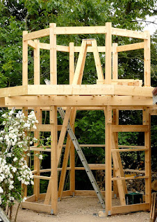
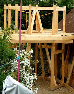
30.6.17

Building the Octagon Pt.38 Tapered pier cladding for absolute beginners. 😳

*

Friday: After measuring up I went off in the rain to collect a single sheet of 18mm plywood for cladding the top section of the pier. I think I can just squeeze four sides out of a full 8x4 sheet if I nest the tapered sections alternately up and down. The fourth side [west] needs to be cut back at the bottom for headroom. The triangles need to be about 80cm wide at the bottom and 30cm wide at the top. The full height of the sheet at 1220mm is close enough. Of course I am being far too optimistic. With the width of several cutting lines and necessary overlaps at the edges I doubt I will see four full sides for the pier out of one sheet of 1220x2440 [4'x8'] plywood. The obvious answer is to shorten the segments so they don't need to be quite so broad at the base.

As it was a very wet and miserable day I couldn't work outside. So I decided draw a plywood cutting plan using PhotoFiltre before assaulting the plywood with my usually untidy pencil marks.

However, I made a simple error in the very first measurement and didn't realise it. Only at the third attempt did I finally see my "deliberate" mistake. I was using half of 400 when I ought to have been using 250mm. i.e. 400-150mm. Grr! The black numerals are the correct measurements from one end of the 8'x4' sheet. The red numerals the nominal widths of each component on the drawing. It's lucky I wasn't allowed anywhere near the real materials because of the bad weather.

In my defense I did actually manage to [deliberately] make each side of the octagon just under a full sheet of plywood. Eight sides x 4' amounted to the 10' diameter building which I needed for my long refractor. 

I also bought another box of 100 Torx joist hangers screws while I was at the timber yard. It is amazing how one goes through screws on a project like this. I am already on my second boxes of the 3" and 4" Torx screws. Thank goodness I didn't use nails! I 'inherited' loads of different boxed nails from a neighbour years ago. They have very mild surface rust which makes them incredibly hard to drive in!

Nails also damage things [badly] when they may have to come apart for half time improvements in design. Or to overcome cutting or measurement errors. I am not a professional carpenter so don't expect me to be more than a hobbyist. I much prefer Torx screws and a rechargeable driver/drill to nails. Just make sure to get a really powerful driver with lots of torque on the higher ratchet-clutch numbers.

My almost new, DeWalt is having to be used on the "Drilling" setting all the time for driving every single screw and it really doesn't like it. It is getting harder and harder to return the collar to numbered clutch/torque settings from 'Drilling.' Even the 15. [16?] torque setting has no guts for driving even short 35 and 40mm screws before it soon starts clicking wildly. Big disappointment! So be warned.

Perhaps there's some fancy "snake oil" which professional carpenters use to help wood screws go in? I can still remember a chippy showing me how he rubbed his hammer face on his greasy hair to make nails go in straight. That was way back in my teens, in the last century. I don't have enough hair left to rub every screw I use and I wash my hair every day anyway.

Click on any image for an enlargement.
*

29.6.17

Building the Octagon Pt.37 It's all in the detail.

*
Wednesday 29th June. Getting the [replacement] ladder into place was a real struggle. I had added a lot of 2x4 braces to the lower octagon walls. So in the end I had to push the ladder up onto the obs. level and then lower the ladder [very carefully] down the hole in the middle. Not an easy task for something 12 feet long and weighing nearly 40lbs. Thanks to the ladder's slightly more westward position I have now more headroom as I climb.
  
I went around adding plates to reinforce the miters on the veranda perimeter joists. The image below shows a nailing plate and a joist hanger. I am using specialist Torx screws designed for firmly fixing these steel parts. The shanks of these self tapping screws are a close fit in the drilled holes to maximize the strength and powers of location. I have almost run out of screws so will have to buy more to finish the job properly. I also screwed the footing brackets to the support posts with 3" Torx screws. 

The entire building is very stiff in line with the main beams but not at right angles. If I push hard across the building N-S I can get it swaying by about an inch at 2-3Hz. The plywood cladding should stiffen up the building and kill this tendency to sway. It is amusing to watch the pyramidal pier remaining rock solid as the entire building moves around it. Though it often looks as if the pier is moving instead, it is very resistant to any movement. The cost of all those cladding sheets is a worry. I need eight full sheets for the lower walls. If I have to use 8 more full sheets on the upper obs. walls, as well, then 16x anything adds up to a lot of money!

It now occurs to me that I have a perforated steel strip for stiffening roofs against lozenging. I could try to stiffen the building with this stuff. Since it takes up virtually no room compared with a diagonal timber brace. I was looking at the building yesterday and there are no clear runs for large, timber braces.

Cladding the top of the pyramidal pier will help to further stiffen it. I have been trying to imagine a suitable space for the drive electronics within the upper pier for weather protection. The plan is to clad the top section with ply first and only then to trim back the slanting tops of the 4x4 posts. That should ensure they all end up perfectly flat for the mounting base plate to rest on. I may add a plywood sandwich first for a more secure fixing.

A sturdy central [threaded] stud will hold the mounting down and allow fine rotation in azimuth for alignment. It is completely impossible to rotate the pyramidal pier itself as it is bolted to concrete footings.

Thursday 29th: The threat of rain limited my options so I attached a 1x6 larch skirting board to the bottom of the nearby shed. Heavy rain stopped play just as soon as the job was competed.  The idea is simply to keep any rodents out. A task previously left to a row of old house bricks and heaped gravel for decoration. The gravel was a useful indicator of excavation but was never visibly disturbed. A sprinkling of the new gravel on top will leave it looking a lot tidier and less likely to splash mud or sand onto the cladding boards.

Once I have trimmed back the projecting timbers of the obs. building I shall have to add guttering to the shed eaves. If the shed roof [or observatory] rains down into the shady gap it will be very slow to dry. Probably increasing the chance of rot.

The image shows the exposed top of the ladder. The present mixture of loose boards and spare 2x8s is just a temporary working surface. The ladder will eventually be tightly surrounded in larch floorboards. Which is why I added the longer joists to allow close and firm support on either side. It would not only be dangerous to have large openings in the floor but would make transition from ladder to observatory more difficult than necessary.

The ladder is designed to rest against a wall, or other hard surface, at the very top of the handrail extensions. I am resting the ladder firmly against a 2x6 joist at the top tread. This will prevent the ladder top putting too much inner pressure on the obs. cladding plywood. While still retaining enough outward pressure to provide the necessary stiffness in the handrail extensions. I may add a wooden cross brace with holes cut for the rubber end plugs to closely locate them against all lateral movement. You never know when you might need that extra strength when carrying up a large or heavy object and need to step sideways while clinging onto the handrails.

Anybody else building such a 2-storey observatory arrangement should seriously consider putting the top of the ladder and trapdoor on the south side of the pier. Assuming they intended to use a refactor or SCT, of course. I checked and I do have plenty of room for the long refractor focuser to clear the handrail. Most observatory owners would probably not choose to pierce the hatch opening with handrails. Having the ladder just there may eventually get on my nerves. I seem to spend a lot of past observing time enjoying rising planets or the Moon in the eastern sky. Primarily because that was the only clear sky available to me!

For imaging handrails or trapdoors won't matter at all. Because I won't need to stand just there. I could have cut the main beams and heavily boxed in the gap where the ladder would fit but didn't want to weaken the structure. In retrospect I could have had a square beam structure. If I double up the 7" refractor with the 10" f/8 Newtonian then I will probably want to stand to the south of the pier anyway. Compromises are inevitable in such a situation. I shall just have to be very inventive in providing a suitable trapdoor/hatch to avoid accidents or silly tripping points.

I seem to have settled on a hinged design of hatch. Though a sliding one might make more sense. It can be pushed into the pyramid pier when open and then return to its normally closed position covering the top of the ladder. Such a design might avoid open gaps in the floor. A flap, hinged jest beyond the ladder top, would need to be tapered to slip inside the tapering pier framework. A sliding hatch cover could be as wide as the inside measurement of the handrails. That said, the taper portion of the hatch would lie well inside the pyramid when [normally] closed. So any gaps with the floorboard would be well beyond accessible traffic areas.

One slight worry is the density of 1.25"x5" larch floor boards if I used that for a floor matching hatch. Lifting a large hatch [minimum 52x90cm] might involve considerable effort pushing from below. Suggesting the use of a pulley system from the ground floor prior to climbing the ladder. The hatch would be tilted well back from the ladder so there would be no danger of it dropping unexpectedly when open. A counterbalance weight might be appropriate if the system was simple and absolutely foolproof. Then the hatch could be dropped down more safely when up in the observatory.

Unfortunately it is not possible to hinge the hatch to the pier. However convenient that might be, it would instantly short circuit the pier's isolation from the building. Any means of counter-weighting would need to avoid wires or cords running across the floor. So it would need levers going upwards and backwards [@ 45°?] with the weights hanging down under the veranda.

Click on any image for an enlargement.
*

27.6.17

Building the Octagon Pt.36. Summary and a few new images.

*

Monday 27th June 2017: Adding new joists to fill in the gaps caused by the huge, pyramidal pier and large ladder.  

Here I have added some more images to better show the buildings construction from different angles. The octagon was deliberately chosen for visual interest. The shape makes a far more decorative, if ridiculously tall, gazebo than a simple rectangular [brutalist] block. The octagon more closely matches a circle.

The rotating roof, or "dome" will turn on a ring of wheels mounted on the very tops of the eight support posts.

The observatory floor needed to be high enough to allow me to see above shared boundary hedges. None of our neighbours, in 20 years, have shown the slightest interest in hedge clipping. I have a go every couple of years but the prickly blackthorn hedges are now over 12'.

Our modest rural cottage dominates the southern boundary of our property. Often denying views of the Moon and planets from the back garden. The house does still shelter me from the major airport, landing strip "security" lights of neighbours to the south and west.

The view from the west shows the four [2"x8"] main beams running east west. While the obs. floor joists run north-south.

All of the observatory floorboards [and planks] are still loose and required for my safe movement around the obs. floor as I work on the joists.

The problem throughout was to lift the observer and telescope high enough to be able to see enough sky in the arc from east to west.

The building is based around an octagon of 4x4s resting on carport anchors as footings. These posts are tied together with multiple braces and support a largely decorative veranda. Whose primary purpose is to visually enhance what was really a simple and boring octagonal building.

The veranda added weight and girth which needed to be carried by the posts. This was achieved, on the advice of CN forum's observatory building experts, by adding the four main, horizontal  beams. These are supported by timber "brackets." Each of which is screwed, bolted and fixed with building adhesive to the relevant posts. The observatory floor joists were then laid over these beams.

A view from low down in the south, looking north. The camera distorts some of the straight lines but the basic construction can be easily seen. The direct entrance to the building from the south has been left wide open to ease access for building materials. It will eventually be closed off with an access door. Possibly with a decorative porch to protect the entrance from winter weather. 

The large ladder, with handrails, was deliberately chosen to avoid accidents while climbing to, or descending from, the observatory floor 'upstairs.' The ladder was housed inside the building to avoid ice and snow preventing its safe use in the dark when I was very likely to be tired and even older than I feel at present.

The building will eventually be clad in vertically grooved, sheathing plywood for strength, long life and shelter. A simple handrail will be provided for safe use of the veranda. The wall above the veranda is insufficient to provide a remotely normal, door height. So I had absolutely no desire to be balancing on a snow or ice covered platform, in the dark, high above the ground, while I crouched low to enter or leave the observatory. Safety helmets shouldn't be necessary for hobbies.

Hence a normal access door at ground level and the oversized and overbuilt internal ladder. This will allow me to carry essentials, like a laptop or camera in one hand, while I climb in reasonable safety. All the while sheltered from wind and weather. 

The ladder treads are broad and ribbed to provide a high level of balance, feedback and adhesion missing from a 'normal' runged ladder. Ask yourself if you would be happy climbing constantly to your own first floor on a runged loft ladder. If it were a normal building you would probably prefer a normal stair and lighting. My choice of ladder was made very precisely for all of the "normal" reasons of comfort and safety.

I know I am repeating myself frequently on my blog but most visitors will probably just dip in here and there. Perhaps interested in some aspect of my reasoning and choices for some part of the construction. I try to share as many images as a slow visitor's connection will allow. Rather than being arranged as a decorative elements in my wordy discussion of the detail. All of which has been gone over hundreds of times as I analyze each aspect, only to change my mind in the end. Or have it changed for me by a much better idea. 

Suggestions are always valuable if only to make me think outside the box. What you see here has evolved from plans for a simple, square, exposed platform attached to the shed rafters for observing and imaging. My seemingly endless discussion [usually with myself] is my way of covering every potential angle or avoiding costly mistakes. I am most grateful for those who had a hand in making it a much better design than I could possibly have managed alone. 

My long suffering wife and "lifetime hobby widow" has also been incredibly supportive and helpful. Endlessly forgiving my obsession with seeing the project through to completion. Repeatedly making useful suggestions which I had completely missed. Trimming back specimen 20' oak and willow trees she had grown herself from carefully selected acorns or cuttings. Unfortunately they had grown up on the only site available for my long planned observatory.

Do you know anybody else who would completely voluntarily work for days on end? Digging, loading and wheel-barrowing 20 tons of sand and gravel? To be wheeled in from the distant drive gates the 40 yards to the building site? 

Would they still do it cheerfully at 70 years of age? Could they even imagine themselves doing it? Are they remotely fit enough both physically and mentally to do it at a third of Her age? Without any demands for reward or revenge. Or pound of flesh to be exacted in payment for services well beyond the call of wifely duty? I am indeed fortunate to have shared half a century of such endless "fun" with my lifelong partner. For those who are interested my wife is petite and extremely camera shy.

An update on my damaged observatory ladder. It was quickly replaced on safety grounds. 👍


Click on any image for an enlargement.

25.6.17

Building the Octagon Pt.36 Joists and ladder clearance.

*
The image shows the view up the ladder towards the intended hatch or trapdoor area. For scale, the ladder is parallel sided and 60cm or 2' wide. The four arrowed joists are new, much longer than previously and have been re-sited from their original positions. 

The problem is providing maximum support for the obs. floorboards while avoiding projections into the path of anyone climbing the ladder.

The trial floor board on the left prevents normal use of the handrail and will need to be narrowed. The joist on that side will also need to be shortened and perhaps mitered to improve hand clearance on the handrail.

The full cross joists at the top of the image is sited at the minimum head clearance position when climbing. I have to lean back with my arms straight and my hands on the handrails to be able to reach that joist with my head. Anything nearer risks a potential accident in the pitch dark.

The hatch itself will probably need to be tapered to pass between the legs of the pyramid while being lowered. All of this could have been avoided if I had built a chimney block pier instead of the pyramid. The ladder could then have been parallel and close to to the nearest side wall. Instead of being placed at right angles and right out in the very middle of the lower floor.

A costly decision in terms of the freely available space. The widely splayed pier legs block normal access to large parts of the ground floor. Particularly in the area behind the ladder. If the pyramid proves not to be stiff enough in practice I shall have the perfect excuse to start building a chimney block pier.


Click on any image for an enlargement.
*

23.6.17

Building the Oxctagon Pt.35 The ladder arrives [damaged!]

*
After waiting an extra day, because the original ladder was bent in transit, the second one proved to be bent as well. The quality of the ladder itself was fine. It perfectly matched my needs as to its exact height to the top step and the 60cm /2' width was very generous. 

The 1m [40"] handrail extensions and the height of the handrails from the ladder side rails was also perfect to match the geometry of their installation. Some ladders go mad with handrails and raise them to ridiculous proportions above the ladder. 

The entire ladder is made of aluminium profiles, all [neatly] welded construction and with generous diameter stainless steel[?] handrails. There is nothing to rust over time. The treads are ribbed and also of generous depth at 4." It felt rock solid and very secure when set up against the shed gable end. All of my builder's ladders seem almost flimsy in comparison.

However, both handrail extensions and side rails were bent at the top tread by a fall or heavy object impact on the side rail[s]. One bent outward and the other a matching angle inwards. A deep dent/scratch at the site of the bend strongly suggests a heavy impact or fall was the most likely cause. The wrapping of welded polythene was well holed from careless storage or transit.

I have contacted the dealer, with several attached images of the damage, and await a response.

In order to fit the ladder, with minimum internal obstruction to the observatory, I had to move a joist. In steadily falling drizzle I worked my way all over the structure removing screws. Off came three of the veranda perimeter joists too. Just so that I could reach the screws in the joists hangers at each end. Finally I was able to move the joist towards the western support posts. Doing so by enough to allow the ladder handrail extensions to just reach the outside wall. A proper brace will be needed just there.

BTW: If Jumbo's technical, telephone expert, or any of Jumbo's Danish dealers are reading this: The lean angle of Jumbo warehouse ladders [Dk.lagerstige] when the treads are horizontal is 70°. Not a lot of people know this.

Saturday: Spent a while distributing gravel across the site to stop sand being carried everywhere on my footwear. The bare sand was even splashing up on the timbers when it rained. Finished just in time before a downpour. That will help to clean the gravel of any fine dust. So it will be even cleaner to walk on. It certainly looks a lot smarter and is much smoother to walk on.

Spend some time later re-fixing the veranda, perimeter joists. It is difficult to reach the outer corners where no ladder can rest. I need to move more obs. floor joists to cater for the pyramidal pier and new ladder.

I plan to have an access trapdoor which is hinged just behind the top ladder tread. The trapdoor will drop down between the extended handrails to rest on slightly extended joists between the pyramid legs. It is difficult to provide support when anything placed there obstructs my climbing the ladder. I have tried temporary battens to check headroom and there isn't a lot to spare under the pyramid. A more normal, column type pier would make an awful lot more sense. I just don't want to get involved in concrete foundations. So I will just have to put up with what I have built. I may even think of something else altogether for a new pier.


Click on any image for an enlargement.
*

21.6.17

Building the Octagon Pt.34 Belt and braces.

*

Wednesday and it is far more comfortable in the mid 60s F. I decided to fix the braces around the octagon for reinforcing the cladding plywood. By increasing the nailing area the triangulation is greatly improved because the plywood cannot buckle or flex under compression loads. The plywood fixing 'nails' will actually be screws in this case of course. I soon ran out of 80mm fixing screws so will have to go back to the timber yard before I can finish the 2"x4" braces. The "doorway" to the building is still wide open for easy access.

A heavy duty, aluminium warehouse ladder has been ordered. With 4" deep treads and an extended handrail on each side it should be ideal but rather expensive.Shopping around online produced a price reduction of over 1/3 compared with some other dealers.

I was able to ascertain the width at 60cm [2'] and length but even the "manufacturer" could not tell me the lean angle. I rang several of their dealers because the "manufacturers" do not deal directly with private customers. None could tell me the slope angle in use. Best guess was 65°. We shall see [hopefully] tomorrow.

If the treads were simple ladder rungs then it wouldn't matter. But who would set up a set of steps with the treads at anything but horizontal? It was like banging my head against a brick wall trying to get the "manufacturer's" idiot on the phone to agree to this basic principle. So I hung up in the end. Why do they employ such people?

Provisionally I have plans to point the top of the ladder towards the south. This is the least trafficked area of an observatory floor housing a refractor. The ladder will probably lean against the doubled 8" beam. With the handrail extension reaching towards the obs. wall out of the way. Providing a secure transition from climbing to actually standing in the observatory. I still can't clad the top of the pier with plywood until I have the ladder here and set up. Otherwise I have no idea of the headroom clearance under the pier.

Thursday: Showers while I wait for the ladder to be delivered. I've measured and don't think the ladder will go between the pyramid legs to the south.  So it looks like West is the only sensible direction. Though that means the trapdoor is on [probably] the busiest side of the observatory. I have spent years waiting for planets to rise in the East behind the high hedge.

Once the rain stopped I set my double ladder to 3.8 meters in length and tried to get it into the building. Not with any great ease! Even with the much narrower ladder, than that I ordered, it was a real struggle to thread it through the woodwork. Then I received a call to say that the ladder had been damaged in transport and wouldn't arrive until tomorrow. I was advised to check it carefully in case of damage to that one in transit.

After careful measurement of the few product images online I have settled on 70°. Assuming this lean angle of 70° I can set the ladder up for the extended top to almost touch the inside of the eastern observatory wall. The problem is clearing the joist which crosses through the ladder's likely path. I shall have to move the joist nearer the support posts so that the ladder can rest safely against it. At the moment it is tied to the far side of the joist. Which makes climbing slightly tricky. The handrail extension could be a real nuisance if it juts out very far into the observatory. So it would be best to push the ladder right towards the obs. wall. That will minimizes any obstruction to eyepieces and cameras on the long refractor.

Trying lengths of joist under the pyramid pier showed that fitting new joists increases the headroom problems at certain points of the climb. I shall have to be rather creative if all the floorboards are to be adequately supported. I still haven't been able to imagine a safe trapdoor arrangement because I don't know where it will need to be or how much headroom it needs. Most loft ladders stow away either it above or all below the ceiling involved. My ladder will permanently pierce the aperture where the trapdoor will be situated.  The southerly orientation was impossible due to the structural beam getting in the way. I could hardly squeeze my shoulders though the pyramid by the time I reached near obs. floor level.

I had another look at the potential joist spacing and it would actual improve. i.e Become more equally spaced if I moved two whole joists. Quite easily done thanks to my using Torx screws to fix it all together. Had I known the pier base would expand so dramatically I could have saved myself cutting the obstructive joists and simply moved them aside. The same with the ladder. The nearest joist need only have been moved a couple of inches.  Until I have the real ladder in place, at the correct angle, I cannot move anything.

The self-compacting sand and gravel is ideal for its purpose [compacting] but is neither a pretty sight nor particularly user-friendly. The dark sand 'travels' with contacting footwear. I shall have to fetch some sharp chippings to tidy up the appearance of the whole site. Rounded gravel never beds down and is like wading through mud if accumulated to any useful depth.

While I was 'upstairs' I tensioned a red cord around the outer edges of the eight support posts of the octagon. This gave me a much clearer idea of the dividing line between the octagonal obs. floor and the outer veranda. It is odd how small the observatory floor seems compared with the ground floor.

Click on any image for an enlargement. 
*

20.6.17

Building the Pyramids Pt.2 No rise and fall pier.

 *

Monday morning: I made a shorter, 90cm tall, pyramid adapter but it offered no real advantage. I had made the middle post 4" shorter to fit the screw jack in there but there was nothing to locate the posts or adapter. It was all too unstable and downright floppy! Most of the time it is just the obs. floor joists and floorboards keeping the pier under control.

So now I've made a simple, crossed 4"x4" [using a halving joint] with an alu. top plate. This will rest on top of the pyramid and provide the necessary 4" spacing for a 12" square, thick plywood, top plate..  It will also locate the tops of the pyramid legs to a clearly defined height.

The posts can then be scribed using a guide of known depth and the posts compound mitered to the line. I really ought to fetch a sheet of plywood from the timber yard to clad the top of the pier. At present there is nothing to stop the pyramidal pier posts from rotating and sliding about relative to each other. I will then be able to judge whether further bracing is necessary.

It is already 77F [25C] again so it will be a long, hot afternoon. It was too, as it crept toward 78.3F in the shade. Before going in for a cooling shower and dinner I decided to fix the feet of the pyramid, pier posts. While adjusting the bracket height on one foot I had noticed another had lifted right out of the brackets. A couple of screws per bracket, four per foot, fixed that. Suddenly the quadpod felt very different!

It hadn't occurred to me that the feet needed to be fixed to achieve geometric stiffness. I had assumed the sheer weight involved would, quite literally, hold everything in place. I was obviously wrong.

I had no time left to investigate further. The tops of the posts are only using friction with the cross-shaped marking guide for location. Fixing the plate might have a similar, beneficial effect on the geometric stiffness of the pyramid. Or I could screw through the legs into the cross to achieve a more precise location. Just to see the effect. I have some long, hex-head roofing screws which might do the job. Nothing else I have is remotely long enough except for studs.[All threads] I'll be back tomorrow.

Tuesday morning: I applied two 150x6mm, 6"x1/4" roofing screws to the top of each post at right angles after drilling. The screws locked up the top end quite nicely and re-tightening the footing brackets has made for a rigid pyramidal structure.

There is a natural resonance when the pier is thumped. This is due to the un-damped free length of the 4x4 posts. Cross bracing near the middle should kill the vibrations. Though too much mass should not be added. Or it could seriously lower the resonant frequency and actually make things worse! Having the braces rise in steps around the pyramid should safely remove the fundamental resonance.

Cladding the upper part of the pyramid in plywood will help to damp any vibrations by shortening the free length as well as adding its own extra stiffness by triangulation. I have to be careful not to hinder the free climb by ladder up to the obs. floor. With the ladder now rising through the pyramid there isn't much headroom on the west side if I completely close off the top half with plywood. I could line the inside of the top of the pier as well as the outside. The box sections produced should really stiffen things up.

I still haven't found a suitable and affordable ladder with treads. So ought to avoid making one impossible to climb by obstructing the climb. The ladder's inclination is an important factor in providing safe headroom. I tried changing the angle of my normal ladder and it did not help head clearance at all!

I could climb to the veranda first but that introduces other problems. Door height to the Obs.would be limited. Then there is the matter of weather. Having to clear snow [or ice] off the veranda just to get into the observatory would be a bore. Which is why I have chosen ground floor access to an internal ladder. Snow can lie here for several months in a bad year.

Click on any image for an enlargement.
*

18.6.17

Building the Pyramids Pt.1 Rise and fall pier?

 *

Interestingly, the pier key offers the potential for mounting rise and fall. The problem is not being able to fit anything [like a jack] between the pier and the obs. floor. Though that does not preclude a scissors, screw jack from being inserted into the pyramid itself below the key. It just needs the support for the jack to be fixed to the pyramid instead. The pyramid would need to be modified to allow sliding motion without any play [at all.] Something better than sawn wood rubbing against sawn wood would be desirable.

A rather quick drawing proved to be out of scale.
The pipes are only 3/4" larger than the 4"x4" pyramid posts.

A  typical car scissors jack provides about 8" of travel and the load would be relatively light compared with a car. A hand crank on a wheel in place of the jack's fiddly drive rod arrangement would be beneficial for regular use. I also have to brace the pyramid lower down to stop the timber adapter from rocking.

So I might as well consider rise and fall in the design. I have a long length of 120mm square [4.7"x4.7"] alloy tube with 5mm wall. That would be idea for the piston movement and it is quite close to the 4" timber I am using. Far closer than my drawing would indicate! There would be enough tube to provide a little over 60cm or 2' lengths for four, rise and fall , "pistons." Perhaps that's not really enough for stability when raised by 1/3 their length?

Having wasted weeks playing with different pier ideas it seems I am going off on another wild tangent. Perhaps I should go with the five posts adapter and return to "rise and fall" later. By then I should have had a chance to make some serious progress elsewhere. My first ideas are not always the best solution and they usually need time to mature into a better form.

As it was a hot and sunny 77F, it seemed like an good opportunity to make it feel even worse. So I dug holes and buried concrete footings to support the pyramid pier. Fortunately I was able to enjoy a little shade from the floorboards which I had left down on the joists upstairs.

Here, scraps of timber are used to locate the concrete footings at the correct angle in the excavation. Each off-cut was removed as I tamped self-compacting sand down firmly around the block with a batten.

I decided I would tilt the concrete blocks to follow the line of the posts. My fuzzy theory being that there would be a spreading force between the pyramid's feet. Getting the lean correct involved a mirror laid on top of the block. By sighting down the sloping post I could see my own reflection. The brackets provide fine, height adjustment by means of a 12mm screw. Which may become useful over time.

No doubt others will say that the forces on the pyramid's 'feet' are all vertical. Or will say the footings blocks are not necessary. They, like myself, have probably overlooked frost heave. We do suffer from annual, if short term, permafrost here. The double gates to the drive regularly droop in winter as the posts move. My feeling is that the footing blocks and brackets will provide solid, frost free location. Which will also save me having to add physical braces between the pyramid legs.

Only experience will tell if I was wrong to use the footing blocks and brackets. The disturbed sand and gravel will soon settle after  another day of my going mostly backwards and only a little forwards.


Click on any image for an enlargement.
*

16.6.17

Building the Octagon Pt.33 Timber pier adapter.

*

I couldn't just bolt the heavy mounting to the top of the pyramid and hope it stayed up there. It needed a bigger footprint and a transition from sloping to a flat surface. So I needed a timber adapter. Adding five vertical lengths of 4"x4" in a cross form would spread the tops of the pyramid legs in both directions by 4". See diagram alongside.

Four shorter pieces of 4x4 cut precisely on the miter saw could help to lock the tops of the pyramid posts together. The image alongside shows simple off-cuts of 4x4 propped on top of the pyramid posts. The matching, compound miters have yet to be cut on the diagonals.

The five vertical posts ion the mock-up are much too tall at the moment. But they rested safely on a platform placed between the pyramid legs. This allowed me to to judge exactly what I needed without risk of the whole thing toppling over.


I can glue the five vertical, adapter posts together to form a solid, timber key. Which can be simply dropped between the tops of the spaced, pyramid legs. Or pushed up from underneath if I had that much strength. There would be five meters of 4x4 in the timber key.

This is a  closer view of the arrangement of four pyramid, five vertical posts and four shorter, mitered blocks to make a 3x3 post form. For an overall sized platform of 12" square.

The pyramid would become too tall with the mitered blocks shown in the corners. So more pyramid trimming is obviously required. Which probably means taking the pyramid posts down again to trim the legs cleanly and precisely to length with the miter saw.The alternative is to cut off the tops of the pyramid legs to make them level. Though that would rob me of the stops provided by the short blocks. The key would literally fall right through the pyramid to the ground without some form of physical stop.

A heavily built, reinforcing block will be required for the bottom of the adapter to stop it from rocking. This block can be lifted slightly with the mounting's large, azimuth pivot stud [all thread] as it is tightened. By trying to force the pyramid legs apart [against resistance] it will greatly increase the stiffness of the top of the pier.

18mm/ 3/4" plywood cladding will ensure the triangulation of the top part of the pier. It will also greatly improve the appearance of the top section of pier visible within the observatory. I don't think my worries about pier to OTA clearance due to the sloping sides are born out in practice. The angle iron, temporary pier is very similar in slope geometry.

Interestingly, the pier key offers the potential for mounting rise and fall. The problem is not being able to fit anything [like a jack] between the pier and the obs. floor. Though that does not preclude a scissors, screw jack from being inserted into the pyramid itself below the key. It just needs the support for the jack to be fixed to the pyramid instead. The pyramid would need to be modified to allow sliding motion without any play [at all.] Something better than sawn wood rubbing against sawn wood would be desirable.

A  typical car scissors jack provides about 8" of travel and the load would be relatively light compared with a car. A hand crank in place of the jack's fiddly drive rod arrangement would be beneficial for regular use. I have to brace the pyramid to stop the adapter from rocking. So I might as well consider rise and fall in the design. I have a long length of 120mm square [4.7"x4.7"] alloy tube with 5mm wall. That would be idea for the piston movement and it is quite close to the 4" timber I am using. There would be enough tube to provide a decent length for four rise and fall "pistons."


Click on any image for an enlargement.
*


15.6.17

Building the Octagon Pt.32 Burning bridges.

*

Not happy with the timber cross and outboard stays. Poor resistance to torque. It also rocks too readily if the feet are not fixed down. So now I have made the Obs. floor, pier aperture larger by removing a couple of floorboards. I am trying to see how large a regular pyramid I can squeeze into a manageable aperture with the feet right out near the walls.

The 4x4 posts are presently too long for this which forces them too far apart at the top. If I shorten the posts I can no longer use them sunk into concrete in the big pipe if I decide to follow that route. I'll just have to do a mock-up on the ground and measure that instead.

I decided to have one more go at a simple, pyramidal pier  using the 4x4s. As can be seen in the image alongside. I had to saw the posts to 4m in length to be able to fit them together at the top. They are pushed out at the bottom as close to the ground floor, perimeter joists as possible. I removed some temporary floor boards to allow the pyramid to dictate its own needs. It took a lot of lifting and poking the heavy 4x4s through small gaps before there was proper clearance for pier isolation from the building. 

I dropped a plumbline from the top of the pyramid to ensure it was centered over the big pipe. My thinking is that the wider the four legs are spaced the less they will obstruct the ground floor. In fact there is no real point on making the pyramid full height to support the mounting. A secondary pier could easily have been added to the top of the pyramid.

The legs of the pyramid want to slide relative to one another, at the top, so bracing and/or plywood cladding will be required to stiffen the structure into a solid geometric form. Cladding will also make the pier top, as seen in the observatory, rather more 'decorative' than a gathering of sawn 4x4s.

I used up the small reserve of self-compacting sand & gravel to fill in the concrete pipe and flatten the floor. Once that was done I'd have to make a conscious decision to uncover it again. So that rids me of a number of options to worry about. Having a flat floor, at last, provided the opportunity to rotate the ladder by 90°. I shall climb into the observatory through the pyramid, under the mounting, without hindrance and with a free choice over ladder inclination.

My camera seems to suffer from mild, barrel distortion. Nothing I try makes everything look parallel.

Click on any image for an enlargement. 
*

14.6.17

Building the Octagon Pt.31. Piering into the past.

*
The perfect pier design still hasn't presented itself.  There are so many alternatives but none says "choose me!" No arrangement of diagonal braces, tried so far, offers much in the way of headroom downstairs.

With four loose, 4x4 vertical posts to play with, it is not difficult to imagine sandwiching other timbers between them. By using a halving joint two planks can be nested, vertically on edge, between the posts at right angles to each other. It is assumed the four posts are sunk into concrete in the large concrete pipe for stability. Though the dimensions of the pipe are very unlikely to offer enough stability on its own as a foundation block. A large plastic bin bag can provide a waterproof membrane for the inside of the pipe to avoid the upright posts from rotting over time.

The downstairs floor is still not finalized so larger timbers could easily be set on edge as horizontal 'feet' for diagonal braces to be attached. Thus making an oversized telescope pier more normally constructed from metal. Through bolts will ensure a complete lack of relative movement as the braces are firmly clamped in place.

A timber cross of [say] 2x6 just below obs. floor level would help to push out the braces to allow a little more headroom under the braces. A halving joint allows them to cross each other without hindrance and exit the four post pier at the same level.The diagonal braces could even be duplicated form [say] 2x4 for increased stiffness but without making the braces too deep and intrusive.

The image shows the proposed timber feet, upper cross and bracing in orange superimposed on a similar arrangement. The upper cross allows more headroom than direct stays joining the pier posts. Only the two nearest feet and braces are shown for clarity.

Separating the upright posts increases their moment. The greater dimension provides greater stiffness provided they are firmly fixed over spacers and braces over their length. Adding 2" wide braces increases the 8" square format to 10"x10".

The timber feet can be lost beneath the ground floor. Or even sunk into gravel if that is the choice of flooring at ground level. A sheet plastic membrane in the form of a tray can ensure the gravel remains dry inside the building. So rot can be avoided. Using gravel of the usual angular chipping variety will enure it settles compactly. Placing the outer ends of the timber feet on concrete footings will ensure a lack of rocking. Separating the footings from the octagonal building's footings will reduce vibrations travelling between them.

The next image shows the 2x6 cross one meter [40"] in diameter inserted between the posts. The posts have also been spaced by 2" at the bottom and clamped with ratchet straps. The diagonal stays are 2x4s clamped to the timber cross to get a feel for the latest pier arrangements.

The pier still rocked because the braces were not properly anchored at ground level. Anchoring would seem to be vital even if heavy timber feet are employed. Though the heavy timber feet are still only optional if the diagonal braces are bolted directly to concrete footings. The triangulation provided by the diagonal braces is the vital feature. Whether they are attached to feet or concrete footings is [hopefully] irrelevant. Though the timber [feet] pier joists would probably provide further leverage against the pier rocking if firmly anchored.

It is fascinating how the wooden pier stays upright just standing on sand. You certainly wouldn't want to do this anywhere it can fall and injure someone.  It weighs a couple of hundred pounds and has 12' to fall from the top! With the floor aperture easily restraining it, the pier seems remarkably docile when upright. Otherwise it wouldn't be remotely so easy [nor safe!] to keep experimenting with different stays.

Click on any image for an enlargement. 
*
 

12.6.17

Building the Octagon. Pt.30 Hooray and up she rises!

*

A simple quadpod of 4x4 timbers makes an incredibly strong structure. Faced with the need to lift the four concrete footings from inside the pipe I opted to use the chain hoist.

I simply wrapped one lifting strop around the crossing of the posts. Then looped another strop through the first with a figure of eight knot. The chain hoist was hooked onto this hanging strop and the hand chain whizzed though to bring the lifting hook down to the bracket on top of the first 84lb block. I slipped a sturdy,  stainless steel carabiner into the largest hole in the double bracket to connect to the hook.

There was considerable resistance at first but then the tapered concrete block rose slowly up though the compacted sand & gravel. The next three blocks quickly followed and were laid out between the legs of the quadpod to be buried again. Much more fun than digging with a trowel while grovelling upside down at the bottom of a concrete pipe.

It was interesting to see Archimedes' Principle on displacement hold true as the sand level dropped dramatically inside the pipe. It would be difficult to judge whether a footing would have the same anchorage qualities in open ground. The pipe offered a container to resist outward sand movement. As each block was removed the next lift grew easier. Simply because there was more room for the damp sand to move aside? Or because the sand was already disturbed? Probably a combination of both.

Before I bury the anchors again I have to decide on the quadpod's orientation relative to the building. Do I want to be able to walk straight into the building between two legs? Or pass by a single leg? This could effect the arrangement of the trapdoor ladder. The ladder was already close to one leg when I set up the quadpod to a 4' square base. There should be no contact between the pier and any part of the building's structure.

Then there is the matter of whether four legs are better than three. There is little chance of four legs rocking because the quadpod is not resting on an infinitely hard surface. The footings are likely to sink slightly to even out the base pressure on each. Bracing and cladding a tripod, if it proves necessary, is a much more complicated geometric puzzle than a four legged square pyramid. With all legs orientated parallel to the sides. The octagon would have been simpler to brace had its legs been orientated square to the building instead of being rotated to face the center.

Another day of gales and showers interrupted work repeatedly. I went around filling in gaps in the joists with more 2"x6". With the veranda floorboards intended to follow the octagon sides I have to ensure proper support for the boards. I finally fixed the third side of the veranda rim joists. It was all down to the middle joist pushing the rim joist away from the miters. Once the obstruction had been relieved by just enough the miters fitted nicely.

The compound miter saw is arguably the only reason I have reached this far. Being able to adjust miters and lay the blade over in one degree increments is a revelation. Miters cut with hand saws are strictly for those who enjoy the skill thanks to regular practice and experience. The incredible speed and dead flat cuts of the powered miter saw really have to be experienced to be believed. The minutest shavings can be taken to correct over-length or angle. The downside is that once something is screwed in place you can't easily bring the power saw back to make small changes. Not unless the component is removed again. Which is sometimes possible with screwed assemblies. Thanks goodness I didn't use nails!

If only the DeWalt rechargeable drill had another step or three of adjustable slipping clutch. It just hasn't the necessary torque to drive most screws home even at the maximum '15' setting. So it always has to be set to the direct "Drilling" option. Which means one has to be incredibly careful with the trigger to avoid damage or hand injuries even on the slow speed setting.

I see YT videos of carpenters using these same drills to drive home very long screws so perhaps I may just have a very poor example. Even with a maximum '15' setting it can't even drive home the short little screws for joist hangers! So it doesn't have a chance on the 3" and 4" specialized Torx wood screws unless the "Drilling " setting is chosen. Working on long screws between the joists is fraught with danger from the drill body twisting viciously as the screw head meets the wood! If I can handle 18' lengths of 2x8 or 4x4 working alone I'm pretty sure I'm not lacking in hand strength.

Still undecided how best to proceed with the tall pier.

Tuesday is dry but windy. I have almost finished the 2x8 veranda perimeter joists.Now I need to fill in the empty spaces with short, 2x6 joists to support the veranda floor boards.

Click on any image for an enlargement.
*

11.6.17

Building the Octagon Pt.29 Piering into the future.

*
As a conscientious objector to limited imagination I really had to try the rubber bands on the pier. I managed to find 16 punctured inner tubes and hooked those over the top of the octagon's support posts.

The pier was made into four parallel, vertical posts without any splay at the base. I did not want any 'tripod effect' to alter its natural behaviour. With the 16 "rubber bands" fitted the pier  proved to have a settling time of about 2.5 seconds regardless of how hard I tugged on it. Hitting the pier with my fist had no obvious effect. Adding the few hundred pounds of mounting and OTAs would have increased mass resistance to disturbance. Whether this would provide a serious means of support for a high power telescope is quite another matter. 


So I have now returned to the tall, pyramidal pier of previous blog and forum posts. I think I am on much safer ground with this. Triangular sides and inherently stiff, 4"x4" posts will provide plenty of stiffness. The base can be reinforced with timber to ensure a lack of distortion. Cross bracing is easily arranged. As is sheathing or cladding the pyramid.

I set up a first trial with roughly 4' sides to the base. The posts are presently too tall because i did not want to have to replace them all if one of my nutty ambitious plans failed to succeed.

The image shows the pyramidal pier propped in place. The splayed posts are surprisingly easy to walk through and around. The trick would be to avoid closing the lower area with braces which would impede normal foot traffic.

Leaving the floor smooth, perhaps with a buried base frame of 4"x4s" could be concealed below a plywood or boarded floor of modest height. Or suitable gravel could be used, to provide a solid foundation beneath the base frame, to avoid sinking or listing over time. The ground should remain bone dry under the building.

I planned to use the same concrete footings as before to provide fine adjustment in individual post height. This does not preclude using packed sand & gravel under the base frame to provide a firmer foundation. Perhaps offering a structure less prone to 'ringing.'

The legs will probably want some cross bracing to prevent them vibrating like a struck bar. They may be thick and relatively dead timber but their considerable length could be prone to individual, flexure and vibration. Arranging the cross bracing above head height or providing a through 'corridor' to plywood cladding is easy enough.


Click on any image for an enlargement.
*


Building the Octagon Pt.28. Veranda woes.

*
While pondering endless ideas in my head, like a spinning plate juggler, I have been pressing on with the construction of the veranda. It seems easy enough: Cut two miters and fix a 2x8 on top of the 2x6 joists to match the adjoining 2x8 rim joists. The problem is that there are no fixed dimensions. The 2x8 rests against a 2x6 joist somewhere in the middle. That joist is not even upright because of the twist in many of the timbers. That same joist pushes the 2x8 away from its direct path between the two 2x8s rim joists. A hair's breadth too much here and the 2x8 rim joists miters won't ever meet. Meanwhile the piece is rocking like a seesaw on the very tip of the beam.

So I scrape away at the middle joist as I try to bring the miters together to perfection. Gaping rim joints are completely unacceptable. They are the most exposed parts of the entire construction and will completely dominate the foreground. Lifting and lowering the 1.8m long 2"x8" at arms length, as I sit perilously close to the edge of the veranda, is very hard work!

It goes on for hours. Up and down the ladders. Trim another hair's breadth on the miter saw in the shed. Back out again. Push the timber back up the ladder and let it lie on the joists. Re-climb another ladder to reach the site of the ongoing saga. 

Lift and lower the piece back into place at arm's length, again and again and again. This is only the third veranda rim joist! Once that joint is perfect then I have to start on the far end of the 4th. It too hangs over a drop with very poor ladder access. The slightest misalignment throws the meeting angle of the adjoining miters out. So the piece has to be the correct height, level and perfectly aligned. All the while the middle joist is pushing the piece out over the precipice.

There is no "Chippy's Mate" to help, willing or otherwise. Fortunately I saw the opportunity to clamp temporary support plates under the "wannabe" miter joints. Otherwise I simply couldn't hold the unsupported, 2x8 for very long, out there in mid air. The superb Bessey bar clamps have proved to be the exception to the rule that all bar clamps are complete and utter crap. I suppose they ought to be at four times the price of the complete and utter crap which I already owned.

Both of my hands feel as if they are sprained from the constant lifting. My back and chest are constantly in pain. My legs ache from repeatedly climbing ladders. My regular morning walks help to untie the knotted muscles but I must have been pretty fit to start with. I have to be constantly vigilant and attentive to potential falls. No ladder is climbed without it being set up properly and then tied off to something solid. The next fall could very well be my last. I have been remarkably lucky to survive this long without life-changing injuries.

Click on any image for an enlargement.
*

Building the Octagon Pt.27. Pier tension?

*

Could the pier remain well isolated but safely maintained upright by several of my collection of punctured, narrow, racing bicycle, inner tubes? Each reaching out to anchors under the obs.floor? The lateral forces required are really quite small. Flexible restraint, even when the massive mounting and OTAs are present,  is well within the capacity of a few of these stretchy inner tubes. 

The individual loads on multiple, flexible lines would be very low. Not to mention at right angles to the normal mode of footfalls on the observatory floor.

Have I accidentally hit the creative jackpot for tall pier support? The tubes could easily be linked to stretch right out to the walls of the obs. itself while safely out of the way beneath the observatory floor. Such long chains would have little chance of short-circuiting the pier isolation.

If you wanted a smarter system then there is bungee cord. Probably more flexible and providing even better isolation from building vibration. I bought a load of cheap bungee cord to laminate the cardboard tubes for the 10" f/8 OTA. I'd almost forgotten about that.

The rain should have ended by tomorrow so I can experiment on the restraint requirements and vibrational feedback. Fixing a mirror to the pier and firing a laser pointer at it should provide some useful insight as I hop about on the the Obs. floor. Though the "clog dancing" may be a bit premature until I complete the floor.

The real question is whether the large mass will, by itself, constrain minute vibration at the eyepiece. It is difficult to conceive of any useful damping system which would work over tiny amplitudes at VLFs. Air, fluid and frictional damping work best against considerable movement. The whole thing could, might, will oscillate freely at its natural resonant frequency. Likely at some small fraction of a Hertz.

A tension system would be incredibly easy to implement. It would be safe, practical and easy to change over a large range of tension. It would be extremely convenient if it worked. Being underfloor where there is no traffic. Easily reached from the ground floor with no external factors. Perhaps I should build a test platform on top of the poles to simulate the heavy mounting? Pile bricks or slabs and keep adding more tension to find a nice balance. If there is one.

The system is essentially an inverted pendulum. Well known for its instability. However, if it is restrained to tiny variations each side of perfectly vertical, then the restoring forces required are minute. I could not believe how easy it was to keep four very heavy poles upright by light finger pressure alone. The same posts which were so difficult to lift off the ground and poke through the small floor aperture, had suddenly become essentially weightless. I was an inverted juggler balancing my cane on the tip of my finger from above. Had I found the perfect, vertical balance point I could have restrained the massive pier with a single length of sewing cotton. Perhaps pole-opposed magnets would do the job? But why get involved if rubber bands can mange the job with much less effort?

I could easily spread the feet of the poles much further apart. But at the cost of much greater inconvenience down on the ground floor. Any form of triangulation of a narrow pole to widely spread feet will eat up valuable floor space. Much of the useful volume of the downstairs room would be heavily compromised. The same holds true for sloping guy lines if they cut through the room. Any such additions must also be completely free of the building itself.

Click on any image for an enlargement.
*

9.6.17

Building the Octagon Pt.26 Pier Pressure 2.

*
Friday, and another very wet day, on an and off, as I propped up all four posts for the pier. Thanks to their almost upright stance they are remarkably docile against tipping. The floor aperture restrains them against any untoward movement. I must have been out of my tiny mind to think I can just drop a heavy mounting and OTA[s]on top of this arrangement! The only thing keeping it upright is its considerable momentum. The footprint, inside the pipe is far too small to provide any serious stability.  My [airy] theory about the necessary mass and anchorage being provided at the base was as substantial as the air surrounding the pier preventing it from crashing.

Which leaves me looking at triangulation of the column in one form or another. A suitably massive construction of heavy timbers could greatly increase the footprint with heavy bracing ensuring a connection between the tall poles and the ground. The result would be ugly and fill the interior of the lower building with obstructions to normal movement and usage. A medieval windmill in all but name and originality.

The other, most obvious, alternative would be the use of stranded steel guy lines. Their connection would be best achieved at just below obs. floor level. Having cables descending at 45° would be only slightly less cumbersome than timbers as far as restriction of ground floor usage is concerned. Which leaves one with some form of internal, or external, gin pole [or A-frame] for each cable emanating from the column. A gin pole is not laterally stable to the lines of applied forces. At least not naturally in this universe.

Which means providing bifurcated guy lines outboard of the building. [Simple but not ideal] Or providing a triangular [A-frame] gin pole to stop sideways tipping. With a single, adjustable guy line exiting the building through an aperture to be well anchored to the ground. An A-frame could stand close to the inside or outside of the walls so cause little or no disturbance to normal use of the lower room.

Either option would provide extra perching space for the garden birds. Quite what it would look like is quite another matter. The guy lines would also need total isolation from the building's structure. "Wind in the wires" is unlikely to lead to vibration since observation is unlikely in much of a wind.
The major downside is the orientation of the guy lines relative to the obs. building. If three cables were provided at 120° apart then at least one cable has to come forwards. The alternative is to use the shed alongside as one, high level anchor. The other two would then lead of to the SW and NW where only trees and shrubs presently grow.

The amateur astronomer's more usual approach to tall piers is a massive concrete foundation. A cast concrete, brick or block pier is then raised off the block. Usually with some form of internal steel reinforcing bars or mesh. Hollow chimney blocks have a following. I had already denied myself any wet concrete in the construction of my observatory. I wanted, and demanded of myself, that the site be able to be quickly and easily returned to a bare parking space. Perhaps a suitable site for a normal garden shed. Leaving a vast concrete slab and pier behind for the next owner of a home is unfair IMHO. It denies the new owner any freedom concerning their normal use  that space.

The obvious question which must be asked is: How important is pier isolation from the obs. building? With only one user, who isn't planning on any form of dancing during observations.. how much vibration would actually be carried into the pier and thence to the magnified image? Can the pier be a simple column to take the heavy vertical loads. With normal anchorage to the obs. floor to avoid toppling. Could steel cables be used to anchor the pier to the building itself, with only rather limited isolation, to keep the tall pier upright?

Click on any image for an enlargement.
*

8.6.17

Building the Octagon Pt.25 Pier pressure.

*

It is now Thursday and I have had to uncover all the wood to check for wetness after yesterday's continuous downpour. Some rain did get in through the cheap tarpaulins and anything wet has been left standing up against the building to air in the weak, sunny periods. It was good to be able to check what timber and floor boarding I had left to play with. The 19' long 4"x4" pier posts were also buried right at the bottom of the mixed heap. I need to measure up and cut those to nominal length. That's the problem with repeated visits to the timber yard. The new stuff tends to go on top of a rather mixed heap. The sky keeps going dark so I shall have to keep an eye out for more rain!

In the image I have propped up two 3.6m [12'] lengths 4"x4" posts [outlined in red] of the intended four. This was to check for clearance issues with the Obs. floor aperture. The posts are rather taller than needed by at least 8" and, quite possibly, more.

The temporary [angle iron frame] pier [right] is only a meter tall but might enjoy a little extra ground clearance, at the zenith, with the long tube refractor. Hence the extra height of the pier mock-up. There is always the option of the folded refractor OTA. Particularly if I want to incorporate the 10" f/8 reflector on the same, heavy mounting.

There is an absolute height limit of 1.5 meters [5'] above the rotation ring if the inside of my dome/roof follows a typical hemispherical form. This height could be exceeded with certain Declinations of the OTA around the Polar Axis. The long dewshield, when on the long tube telescope format, has quite a reach at high pointing altitudes. From very fuzzy memory it reaches 11' above the ground with the OTA pointing at the Pole. The image right shows the naked, 7" f/12 telescope tube without its objective, dewshield or focuser.

I am repeating myself here because the 3m diameter [10'] observatory size was specifically chosen to house the long tube refractor. Talking of which: I now have access to aeroplane plywood in various thicknesses. I could save some OTA weight and perhaps reduce some theoretical, thermal issues by rolling a new tube from this material. I made a tube for my 5" f/15 refractor which was remarkably stiff and light. Whether a new tube is really worth the effort is another matter when it is permanently mounted. I would certainly use Epoxy this time around rather than waterproof, resin powder, wood glue. Still, there is no haste to get involved in yet another project until the observatory is completed.


Click on any image for an enlargement.
*

6.6.17

Building the Octagon Pt.24 The Veranda. Pt.2.

*

The first veranda corner to the next side of the octagon towards the shed went remarkably well. The joint was perfect but the far end about an 1/8" low. I think I can live with that because changing the angle would require a minute skew to the miter. It is hard work holding nearly a meter and a half [5'] of 2x8 over your head while dangling from a ladder. So I clamped a nailing plate to the bottom of the fixed joist. This allowed me to rest the new joist while I checked for miter angles and fit on the end of the hand-mitered joists.

Perhaps I should put big red arrows on the images to show the changes? Every one of these images looks almost identical unless you are keeping up with progress. The new piece is on the right close to the shed's eves.

Yesterday evening I put some 2x8s back up as scaffolding planks while I hand sawed the next two joist on the left. It didn't feel safe on loose floorboards sitting right out on the edge of the unfinished veranda. Now I am ready to add the rim joist for the next face of the octagon to the left.

I glanced up at the gibbous moon to see a brightly lit airliner pass straight in front of it. Once I had descended to the ground again I had to walk many yards back to even see the moon over the tall, intervening hedge. It is a shared hedge on the boundary and no previous occupants have show any interest [at all] in trimming it.

I have done my best dangling from a tall ladder but it is mostly very prickly Blackthorn or Hawthorn. It really ought to be levelled to the ground but would need a huge bonfire to get rid of all the debris. Or a very large lorry to take away several loads of prickly branches. Hence the raised observatory just to be able to see over the hedge to see planets rising in the East.

The builder's straight edges which I bought for my 10" OTA have proved invaluable in marking out accurate miters on already fixed timbers. They are incredibly light yet stiff and perfectly straight.

I have been remarkably lucky with the weather. With almost continuous, warm sunshine. Now the weather is set to change to rain and wind. Which leaves me with a dilemma. Should I take down all the loose timbers and cover them in tarpaulins?

If they get wet I can't easily treat them against rot until they dry again. In changeable weather that could take time. Though the veranda support timbers are the most important surface to protect. It is here that rainwater will lie between the joists and planks. I couldn't buy the wood preservative yesterday because the shops were shut.   

I spent a warm, windy and sunny morning fitting the next veranda rim joist on the left. I also [hand] sawed off the extension of the main beam. The second one is marked off with the square and will be sawn off after lunch.

In the afternoon I followed on around and cut all the joists to length after marking with the long straight edge and a square. I am getting quite useful with a hand saw. Rubbing the blade with a tablet of cheap soap has transformed the saw. I used to use a candle to lubricate my saws but that doesn't work nearly as well. I just wish the teeth were still as sharp as when new.

The plan now is to have all the veranda floorboards running parallel with their nearest side of the octagon. This will help to ensure rain running off the roof/dome, or upper building, is shed outboard of the lower storey by aluminium flashing. The veranda will become a separate unit outside the main building's octagon structure.

It will be an interesting exercise in mitering and valuable experience in the use of my adjustable miter square. Built from quality brass, blued steel and rosewood it was bought years ago for a specific job but hardly used ever since. The floorboards inside the octagon will still run from east to west. There is no other logical way of dealing with the large trapdoor and pier aperture which lie side by side separated only by a joist. Talking of joists, I need more timbers to support the Western run of the veranda. I'll also see if I can find some 45° hangers for the joists lying under the veranda's mitered ends.

With heavy rain forecast I lifted most of the floorboards back up onto the upper rim joists. I'm hoping this will allow the structural timbers to dry more rapidly between the forecast rain and showers. Leaving the boards down guarantees they won't dry. I thought of putting a tarpaulin on top but it's a very odd structure to protect in a gale! So it would end up as a sail and probably do more harm than good. There followed a torrential cloudburst!

Click on any image for an enlargement.
*