*
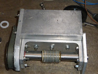
Monday 30th Nov. 36F all day with heavy overcast. Grey, becoming breezy with wintry showers in the late afternoon.A couple of images showing the complete mounting and detailed construction of the RA worm and motor housing.
The mounting was photographed by artificial LED light.
The L-profile reinforces the box section but also presses against the end of the stepper motor inside the box. Hopefully providing another level of stability for the housing. I suppose I could add many more bolts to hold these parts more firmly together.
The sturdy cross sections should help reduce flexure but seem not to in practice. Note how little clearance there is for the motor inside the alloy, box section profile. I have never noticed any heat from the motors.
The motor and worm housing seen from the power socket side. The large slot was necessary to allow the motor power socket to slide into the box section. Potentially weakening the box profile's stiffness.The original channel section worm housing has been considerably strengthened by the added material. Yet still seems to be prone to flexure.
Angular contact
bearings have a shoulder against which the balls roll to provide much
better resistance to linear [axial] loads. While still accepting radial
loads.They are similar to bicycle wheel bearings in this respect.
Once
I have a working set-up I could swap the rather mixed screws with the
correct length of stainless steel, socket head screws for neatness.
It seems the missing ingredient for my mounting is/are flexible, blade type hinges. Thin metal is sandwiched between suitable plates. [Long bevelled strips.] To restrain bending to only the very narrow, exposed strip. Said strip being all but impervious to flexure in any other plane than perpendicular to the required worm movement. A sort of triangulation by "skin effect." The sheet metal cannot bend in its own plane provided it remains essentially flat. Much like a structure can be covered in sheet material to stiffen it.
Even doped canvas has a remarkable effect on seemingly flimsy aircraft structures. Slight hinge movement, perpendicular to the hinge [blade] is all that is needed to achieve efficient meshing. No twist means no backlash. Ideally the "flexor" hinge needs to be close enough to the worm housing to avoid any [series] flexure in its support. Though closeness of the hinge is not vital provided the support structure is stiff enough.
*


No comments:
Post a Comment