31.1.21

31.01.2021 Worm housing, rear bearing brace.

 *

Sunday 31st 29-36F, cold but clear and sunny again. I worked on the RA drive. Making an angle profile reinforcing brace/bracket for the rear worm bearing. I changed my mind about reproducing the same design as last time. It did not tie the Beacon Hill worm housing into the new, bolt-on structure. So I am making a bracket bolted directly to the new structure and the end of the worm housing. 

The most difficult part was carrying the hole pattern over to the bracket from the end of the worm housing. I made a stencil and now have the large [bearing retention] hole drilled. Now I just need to mark and drill the smaller holes.


30.1.21

30.01.2021

 *

Saturday 30th 28/26F Hard white frost but a clear sky.  I am set up for imaging. Not much to see on the sun. The 6" objective is dewed as usual. Dew heaters showing 73F on the digital thermometer.  

I have a metal cap with an inch of insulation inside. A non-metallic cap might help. My keyboard doesn't like the cold!  Lots of keys not working! 

The image shows how lost in shrubbery is my dome despite it being raised.

10.48 31/28F I have just tried a capture but it wasn't worth the photons. The sun has reached 14° altitude.

11.04 32/28F I am seeing more surface texture as the dew spot shrinks. Still 3" across. The dew heater has reached 77F.

12.11 34/30F Became bored so buried another block. To make six. The Ist dew heater has now reached 81F. Objective still dewed. Soft focus. The Astrozap 2nd band reached only 63F for the same setting on the Astrotech 4-way control box.

12.35 36/31F No improvement in contrast.

 13.00. Stopped for lunch.

I made the observation slit 80cm wide on the 3m plywood dome. That looked to be the best scale to me from the outside. So about 1/4 Ø. Though the slit looks narrower from the inside. Not too onerous to keep advancing it to follow the sun with my friction wheel drive. The general opinion seems to suggest 1/3 Ø. Though that is probably more for reflectors and SCTs. 

New dome = 4.3/4 = 1.075m. About 20cm or 8" wider than the present slit. Wide enough?


*

29.1.21

29.01.2021 Another block in the ring.

 *

Friday 29th Below freezing all day and overcast. I have moved another block. Using the plywood, arc templates is proving essential to maintain the correct positions. Plus one more block, after lunch, to make five. The sixth needs to be moved only 4" and is already half excavated. That will be half way. The continuing frosts are making it difficult to penetrate the top two inches of the self-compacting gravel. 

Most of the posts tried, at the five new positions exactly match a joist on the veranda floor. The sixth to the eighth lie outside the veranda. Now I am wondering if I can make the building in two vertical sections. A lower and an upper half. Separated at veranda floor level. It will need serious connection between the two lots of vertical posts. 

The pairs of posts could be overlapped and [coach] bolted though. With my usual trick of sandwiching toothed star washers between the posts fitted around the bolt shanks. Plus hefty roofing washers to avoid the bolts crushing the timbers. They don't build skyscrapers from single vertical beams from top to bottom. Shorter posts or panels would make life so much easier. Something to ponder before I order the metric 2x4s. Shorter lengths would be lighter to handle and faster to erect. With lower risk of bent or twisted examples.


*

28.1.21

28.01.2021 How long is a piece of wood?

 *

Thursday 28th 29F, hard frost with occasional sunshine.

I can hardly believe it, but I have made a huge mistake. My two days of exhausting excavations, for foundation blocks and burying them has gone horribly awry. 

Guess who used the wrong spacer stick? Correct! The blocks were all spaced at 75cm instead of 85cm. I have corrected two blocks but am still too unwell to press on with excavating the others. Particularly with the ground surface now rock hard from days of frost. With many more forecast into February. 

I have looked at potential short cuts to avoid digging up every single block all over again. It doesn't help. There is no point in moving any backwards slightly. Nor leaving any in place. Each will have to be unearthed than lifted out of the hole. 

I have dug a hole right beside the first two. Then levered them along with a shovel. Which was harder than starting from scratch. Because the gravel fell in around the blocks. So I had to bodily lift them out to clear the hole. [70lbs!] Something I didn't have to do when they were laid. I made the hole large enough and deep enough to drop the blocks cleanly into place first time. At least I thought I had. Dogh! 😣

I managed to move another block before lunch. The frost had no real depth. I chopped off the "wrong" piece of wood at block depth. Just to avoid any further confusion.  Having a measuring stick for block depth is vital to avoid having to repeatedly lift a block out of too shallow a hole. It is very difficult to judge the precise depth. The southerly, door post spacing is far more realistic now.

I tried a long [2x4] lever but the hole was too deep to allow a block to be lifted clear of the ground. Which meant the block fell back in. With lots of gravel falling in along with it. At least I tried. I might try moving another block this afternoon. Or not. 

With the sun out I set up for imaging or the first time in ages. There is internal dew stealing all the contrast. I have set the dew bands going but hold out little hope of it clearing. 15.00 29/33F. Clouding over from NE! Sun is gone for today. 

At least I remembered where to plug everything in. Though the laptop battery was flat from extended idleness. I put it on charge and it woke up. Only 35Mbps wireless in the observatory today.

The reinforced RA drive system was a great improvement! No more delay before the image moved. It stopped dead when I released the slew button. Given the huge scale of the sun's image on the 27" screen I was very pleased.

*


26.1.21

26.0.2021 Yo heave ho!

 *

Tuesday 26th. Sunshine. Not feeling too bad after yesterday's efforts. I have walked off most of the pain. Now to see if I can make further progress. 

I managed to bury two more foundation blocks before lunch. One cost me extra time because I backfilled before noticing it was 2" higher than the others. I brought out my long level and double checked. The difference in ground level had fooled me. I was grateful for lunch so I could have a rest!

Regarding panels v individual timber posts: I'll order a load of [50x100] 2x4s in 4.2m lengths. Then try building one panel to see if I can cope with the weight and bulk. Or find an efficient way of handling and raising them. 

One obvious problem with panels is the veranda getting in the way. I can't easily thread panels through the existing structure. Like I could with loose posts. To be followed up later.

Setting up fully clad panels makes them potential wind catchers in stormy weather. Unless I start in the south west where there is least support but no veranda obstructions. Otherwise, I'll have to have most of the panels already built. To go up in one session. That would need preparation up top to allow quick progress. 

Perhaps having the panels only clad lower down would be best. Then they can be more easily threaded through the veranda joists. I'll have a look at the obstruction problems before making any decisions. 

After two days of exhausting digging I had the worst attack of dizziness so far. With all the other nasty symptoms I won't mention here.

*

25.1.21

25.01.2021 Digging down to raise a dome.

 *

 Monday 25th 33F, mist cleared to sunshine. The dome is in the shadow of the neighbour's trees. 

I'm going to try digging my first post/block hole. First I must rake all the pea gravel aside to avoid wasting it.  

You couldn't make it up! Three boulders precisely where I needed to place my first block! It must have cost me an hour to remove the largest. Using a long lever and working the rock slowly up a ramp of gravel. After that I backfilled around the first block to use up some of the loose gravel from the excavation.

It doesn't look it but the block is slightly below ground level.

The second excavation was almost effortless until I found another rock in the bottom of the hole. 

Paused for lunch when I ran out of steam. It has been a superbly sunny morning. In the sunshine I was warm while wearing a T-shirt during digging operations. Stepping into the shade was like walking into a fridge.[37F now.]

The blocks and the posts they support, are deliberately tight to the north and south walls of the octagon. With the maximum variation between the octagon and the larger building in the SW and west. Left in the image below.

I can hardly believe it but I managed to excavate four holes and bury four blocks today. I am rather tired and my back hurts but I shall survive.

The last [wide angle] image shows the tools I used. The arcs were superb for guiding the exact block placement. They are shown touching the metalwork on the blocks and aligned with the fixed rear, SE post of the octagon. I have removed the metalwork from block No3 to avoid tripping over it. I shall probably do the same to the rest as I proceed in a clockwise direction.

My [spacing and depth] measuring stick is lost on the middle arc. The self-compacting gravel still needs to be tidied up and levelled. It carries everywhere on my shoes. So it ought to be covered in pea gravel as soon as possible.

*

24.1.21

24.01.2021 Juggling the building's cladding panels and posts.

 *

Sunday 24th cold and grey with mist but light winds.

Just another mental rehearsal: Nothing to see here. Move along please! 😉

The more I think about the expanded building the more I favour raising pre-made panels. Balancing 2x4 upright posts individually, from an adjustable bracket at ground level, isn't easy. If I assembled the full panels down on the ground they could be shoved against the brackets and pushed upright. Then steadied with a timber brace, or an open, builder's stepladder, leaning against the plywood cladding. The ladder's cross braces at top and bottom, with big rubber feet, would add breadth and friction to keep the panel nicely stable.

I can then climb the stepladder inside the building to fix the tops of the panels together. The depth of the angled, paired [2x4] timber posts does not offer itself to spring clamps. G-cramps would probably slip off. So, I could use roof, nailing plates with screws on the inside faces of the vertical posts. A quick and very secure fix using a rechargeable drill, Torx screws and Torx driver. 

I have 'proper' nail plates nails but they are best added after a secure screw fixing. Screws are not approved of because they are hardened and will break under heavy loads. The nails are short and sturdy and have ridged shanks for grip.

As the panels are raised they would become self-supporting by friction between the long vertical edges. Single 4m lengths of timber would not be remotely stable when upright. They would need something to lean against which retails them to prevent dangerous toppling. Panels give me the freedom to add the top ring afterwards. Rather than relying on it for post fixing security. Panels free me from having to find a nearby joist to get a safe, post fixing.

A panel would consist of two, 4.2m high, metric 2"x4"s at the vertical edges. With at least three, 2x4 cross braces. One at the base, another at the horizontal joint between two cladding boards and a final one across the top. The lower panels could be diagonally braced inside. While the panel cladding provide vital, stressed skin effect bracing it could be subject to distortion under heavy wind loads.

Timber length per panel:  2x4m = 8m. Plus 3 x 84cm = 2.5m cross bracing. A total of 10.5 metres of 2x4 per panel. I'll weigh some 2x4 and calculate the expected panel weight. Online spec is 3.3kg per metre for 47x100 planed timber. 14kg per 4.2m length. So 28kg for two uprights. Say another 10kg for the cross braces. About 38kg + plywood cladding. Quite "lumpy" but not impossible. The diagonal bracing can be added later.

The lower cladding boards would be 9mm plywood, 2.4m high x 85cm wide. The top panels [at observatory wall height] could be added afterwards to keep the panel weight down. Depending on actual experience of handling the panels. It might be safer to fully clad the panel rather than fitting the top boards from a ladder. Which would require at least three hands, several tools plus screws.

I could use a top pulley to bring the panels upright after pushing the bases up against the building. Once upright, I can use levers to lift the panels into the foundation block brackets.

The [12] plywood clad panels would come together with a dihedral between the vertical 2x4 posts. Suggesting I saw long wedges on the table saw to close these gaps. Which would beef up the joints into solid timber. Otherwise there would be a gap behind the vertical edges of the cladding where the panels come together. With no obvious, mutual location on the inside corners. The wedges would help to align adjacent panels. Or [FAR BETTER] mitre the faces of the 2x4 uprights to match the angle at the joint between the panels. Second image.

One problem which might rise is bending of the upright posts as bought. Selection on site would allow the worst offenders to become the short, cross braces.

I will use aluminium, Z-profile 'drips' to protect the horizontal joints between vertical cladding sheets.


*

23.1.21

23.01.2021 Expanded building footprint using arc templates.

 *

After lunch I laid out the re-cut arcs and they fitted perfectly for an inside diameter of 4m. So I moved them over to the octagon and laid them in a ring around the building. Being careful to butt the joints neatly together. Then I measured all the distances between the arcs and the octagon's corners. Finally I measured the shortest route to the octagons walls from the inside of the arcs.

All the figures were safely entered in my notebook. My habit of scribbling on scraps of paper was never very reliable. 

Next I scribed lengths along the inside of the arcs for the new post spacing. Twelve posts spaced at 85cm centres, on a 4m diameter circle, proved to be just right. 

Then I tried an upright rod to see where the new posts would fit onto the veranda joists. It should not be too difficult a task to tie them all into the existing structure. Only in the W and SW did the posts lie well outside the veranda. I shall have to bridge to these with new joists attached to the originals. 

I want all of the new posts to be load bearing. So the octagon's posts can be safely removed if necessary. Though it may prove more useful to leave some of them in place but chopping them off at observatory floor level.  Leaving the observatory floor clear. Right out to the new and much larger footprint. 

There is no further need for the old posts to support the smaller diameter top ring of the octagon. Except in the east. Where I will retain the two original posts nearest the shed.

Now I can go ahead and dig the holes for the 12 new posts. I have a narrow, trenching spade to keep excavations to a minimum. Though it may well prove more efficient to dig a trench at 4m diameter. Rather than digging narrow, steep sided holes with gravel constantly falling back in. The last time I laid these blocks for the octagon was during a dry period. When damp, the gravel is much less prone to flowing downhill.

The images show the template ring arranged around the existing building. The centres of the new building [foundation] blocks and posts will lie on the inside of the ring. Leaving the shrubs on the outside safely untouched. They provide shade, wind protection, colour and interest.

The twelve, much narrower walls, will give the larger building a much smoother, external appearance. Far more rounded than the present, rather flat-sided octagon. I would never build another octagon. Too inefficient of usable space for the ground area covered.


*

23.1.2021 Cross Axis Equatorial mounting?

 *

Saturday 23rd Jan. 36F. The gales have dropped to light winds thank goodness. Largely grey skies but dry. I must try to check the ring template arcs for accuracy when they are butted together with the new angles.

I had a mad idea yesterday while contemplating the remounting of the 7" f/12 beside the 6" f/10 in the larger dome. Or, even mounting my 10" f/8 Newtonian opposite both refractors? 

All of which are exhausting and enormous [sic] time wasters to remove and refit. When having to swap them around on the present mounting. Even though I have an overhead block and tackle to help me. Lifting the telescopes high enough without hitting the inside of the dome is a problem.

What about a cross axis style, equatorial mounting? Sometimes known as the Modified English Mounting. A very long Polar Axis is supported at top and bottom by individual piers in the North and South. The increased dome size offers me much greater freedom to play with this design.

I have a couple of 2m long, heavy, box section tubes in aluminium from the scrapyard. One is 5"x5"and the other 4"x8". With lots of shorter pieces in 4x8 and 2x8. So I can construct any PA length I may need.

Two piers would spread the load and be less prone to azimuth twist [if it exists.] Another advantage is that the counterweights can be hidden above or below the observatory space. I was repeatedly hitting my head on the counterweights with the longer PA shaft on the present mounting. That would need to be refitted with all the struggle that entails.

Perhaps more excitingly: All three OTAs could easily counterbalance each other. The OTA's individual spacing from the PA ensures balance. With no need for a meridian flip. Or even conventional counterweights. Provided it all clears the observatory and floor. The 10" Newtonian on one side of the PA. The two refractors on the other.

The need for the huge, pyramidal, timber pier in the centre of the observatory would simply vanish. I was certainly not relishing having to move the whole thing towards the SW!! Which would mean the total removal of the existing mounting [GEM] anyway. Then moving the massive 4"x4", four legged structure. Plus digging up and re-burying its four, foundation blocks. Not to mention the problem of fitting the huge pier between existing joists and flooring! Which would mean major surgery of the existing structure. The original joists were deliberately fitted around the pier.

I haven't done any proper scale drawing to see what is possible yet with the Cross-Axis design. I may well have overlooked a serious flaw. The huge PA would still need to be firmly supported at a considerable height from the ground. With the southern bearing resisting all the downward and PA+OTAs axial loads. No doubt a 4"x4" A-frame could provide lateral support. 

The axial loads would need rigid resistance without hindering freedom of movement on the ground floor. Both A-frame piers could easily be tied together with timber well above head height on the ground floor. Which would simultaneously guarantee the N-S stiffness of both piers. As well as complete isolation from the building. The increased mass would be all to the good for rigidity of the telescope mounting.

The much higher, north bearing support could be a simple 4"x4" timber A-frame. Perhaps clad in ply for extra stiffness. It could be made of curved and laminated plywood within the dome itself for maximum telescope clearance under the Pole. With the supporting A-frame only reaching as high as the top of the observatory wall.

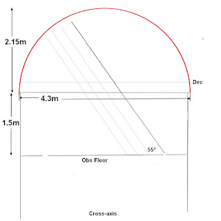
The northern [tall] pier would be placed very near the northern observatory wall. So no real hindrance to movement on that side of the dome. A very tall northern pier would allow a longer Polar Axis. Allowing a far greater choice of southern bearing placement. See the sketch above for the parallel lines. Showing alternative PA [Polar Axis] positions and lengths.

It would obviously be better to have a clear walkway around the southern end of the mounting. To save ducking [or even limbo dancing] under the PA at its lower points. Also to avoid having to move the telescopes just to escape to the stairs. Something to keep firmly in mind when trying different pier/PA geometries. The 55N polar angle is obviously fixed. Its very steepness being an advantage here, I believe. The PA would cover less overall floor area even when made deliberately very tall at the northern end. 

I checked how extensions of the existing GEM mounting Polar Axis would fall: 2.2m to the floor below the axes crossing and 1.3 above to the present dome. A 3.5m long Polar Axis! There would be more room in the larger dome. An alternative, without offering the freedom form meridian flips, is a southerly extension of the Polar Axis down to the floor. Greater stability and resistance to torque effects on the present pyramidal pier. 

Is it really worth the hassle? Probably not. The great difficulty of moving the present, massive pier is ample excuse to build the full Cross-Axis mounting. Far easier to dismantle it and use the four legs for the A-frames. 

The three OTAs would be very bulky and sweep out quite a large volume in the middle and lower, north side of the dome. The height of the Declination axis will control headroom and OTA clearance from the dome above. No problems with clearance above or laterally in the larger dome. Particularly when the OTAs are parked horizontally facing East. Or when I am imaging the sun early in the morning. It should be quite easy to move about beneath the telescopes and PA under most, normal circumstances.

I enjoy the present, south-facing desk on the northern side of the dome. It gives me clear sight of the telescopes and their clearance from obstacles. Including the bare clearance from the desk top during a meridian flip! I am sheltered from direct sunlight by the instruments and the big GEM. The north facing monitor is fully shaded. While I deliberately wear black clothing to avoid any risk of reflections in the already low reflection, AOC monitor screen. 

Can this successful workstation be duplicated to become free standing or even wheeled? Cables are already an issue. With severe limitations on length in some cases. Reaching the telescopes with USB3 cameras attached would need much longer cables. Unless it can be managed wirelessly. No problem having the RA drive at floor level and the Dec drive cable is usefully long.

I imagine the [horizontal] Dec axis would be arranged at much the same height as at present with the big GEM. That would mean the 10" Newtonian eyepiece will be rather high above the observatory floor at times. Though the plan is mostly to image the Moon and The Planets. Which just needs the camera to be fitted, with the telescope horizontal, before starting an imaging session. With remote, motor focusing. Thereby avoiding the need for tall stepladders.

I do not foresee the Cross Axis mounting costing me much at all. I already have all the [scrap] building materials to hand. Or to be sourced in the parts of existing GEM. Such foolish ambition in the middle of a pandemic at my age? Will this madness never end? 😊


*

22.1.21

22.01.2021 Spiling an observatory pad and RA drive progress.

 ~~

Friday 22nd. More gales.

My wife came up with a brilliant idea: Spiling. The gentle art of weaving willows into a bank retaining structure. Just like coarse basketwork. I was struggling to retain the edge of the observatory pad. The entire area had been raised by 3' with nearly 30 tons tons of self-compacting gravel. All shovelled into, then trundled manually to the spot using wheelbarrows. Then dumped, distributed and compacted by stamping. 

The expanded footprint of the intended, larger building places the foundation blocks much nearer the edge of the "pad." Without the safety margin of a surrounding path. 

I had been collecting more trailer loads of gravel but it doesn't go far on a 3' high, 45° slope. A row of posts with willow stems wrapped around them, works even for eroding river banks. So it will be fine as a retaining "wall" for much more limited quantities of gravel.

The gently, reverse tapered foundation blocks work best by remaining safely buried. Rather than lifting or even bursting right out of the ground when the supported building is subjected to fierce gales. So a decent mass of solidly compacted gravel is needed around them.

I spent the morning working on the RA drive. The motor sounds much quieter now. Though what that means in terms of the drive performance is still an unknown. 

Several 180°s on the RA and Dec produced no stalls or unusual noises. It takes nearly four minutes per 180° RA slew on the AWR Simple Handset.[Paddle.]

There is still a sense of slight knocking when I move the telescope quickly up and down by holding the draw tube. That's using about 3.5' of leverage. This is with my finger tips resting on the free end of the worm shaft. It is certainly a vast improvement on the visible rocking I had before the latest mods. 

A new angle profile bracket, bracing the motor end, is next. The upstand will be covering the free end of the worm housing. The four, bearing clamping screws can lock up the angular contact bearings if overtightened. Though they still don't provide the necessary immovable resistance of a solid plate.

I opened one dome shutter to have better light. Then had to quickly shut it again because of the nasty gusts of wind. I had already turned the dome slit well out of the wind direction. The trees are all rocking and there is none of the promised sunshine.


*


21.1.21

21.01.2021 RA drive progress.

 *

Thursday 21st 43F, 45mph gales but mostly dry. Even a little sunshine. 

I have largely completed the rebuild of the heavily modified RA worm/motor housing. The new, 260T belt now fits perfectly without an idler. 

I carried the heavy drive unit upstairs to fit it onto my massive, home-built mounting. Then realised that the changed, worm offset needed new mounting holes for the drive assembly. I shall attend to that after lunch. I hope it has all been worthwhile.

The pre-loading on the worm bearings is applied by washers over the bearing retention screws. The bearing having been made to protrude very slightly beyond its housing with a thin shim [washer] on the worm axle. I had made an angle section brace for that end of the worm. Which no longer fitted after the worm was offset relative to the motor. I shall soon find out if I need another one.

I had to remove the main motor plate from the mounting to make new slots. Then rebuild the bottom end of the Polar Axis. This required leaning on a long length of brass tube pushed onto the RA shaft to help to balance the mounting. 

The increased, clearance problems between the motor housing and the pier required more, time consuming woodwork. It would have been quicker to remove the motor assembly.

The RA feels much "stiffer" now as the telescope is manually rocked up and down by the focuser. Without the previous sponginess. It was too late to try the drives by the time I had to call a halt.

The noise from the gales up in the dome was unbelievable! Mostly from the rubber skirt being violently shaken or slapping hard against the structure. There was zero sign of the dome itself lifting or moving. I shall avoid having a soft skirt on the new dome.


*

19.1.21

19.01.2021 Ring template arcs and RA drive.

  *

Tuesday 19th: A grey, damp day. I trimmed the ends of the arcs with the jig saw. Then cleaned up the cut edges with the mini router against a straight edge. Far too wet to lay them out on the ground to check their accuracy. Heavy rain forecast for tomorrow. After thick mist overnight. 

Wednesday 20th: Rain and wind. The hole saws have turned up today. Now I can finish the reinforced RA drive motor/worm assembly. It is no use having a massive mounting, capable of carrying heavy loads, if the drives don't match in performance. 

I had grossly underestimated the weakness of the Beacon Hill worm housings and bearings. It wasn't until I started looking at up-market, commercial mountings that I realised the best had one thing in common. The worm was housed in a boxy casting with very high, inherent stiffness. NOT in a cheap and flimsy, channel section, aluminium off-cut. Barely wide enough to house the plain, ball bearing races!  

The 26mm hole saw produced a nearly 28mm hole. I had a carrier with the correct thread but the hole saw swiftly became eccentric in the hole. This, despite my drilling a pilot hole just undersized. Fortunately the bearing wouldn't enter the hole. So it will be safely restrained against linear movement. Which would otherwise cause backlash. I also need to apply end loading on the angular contact bearings. 

After lunch I shall reduce the boss on the larger pulley in the lathe to ensure clearance. Sawing out the motor & worm plate from the scrap section would be easier and more accurate on the mitre saw. Except for six, 5' x 5' sheets of plywood leaning against that same saw! It looks like being the jig saw which gets the task. And did. 

A coarse toothed, DeWalt metal blade went through the 10mm aluminium plate quite quickly. I put a few drops of lamp oil in the cuts. The drive unit went together smoothly once I had reduced the large pulley hub to 25mm. Now I just need to tidy up and refit the stainless steel, socket head screws and Nyloc nuts.  

As of yesterday, Google Blogspot has suddenly lost its quick edit button. I am not alone! Added to the newly created farce in trying to edit text around and when moving images, one must assume internal, evil intent. Obscenely overpaid, new broom? Working several floors above their qualifications for the task? 

*


18.1.21

18.01.2021 New dome will have spherical shutters?

 *

I have had my order confirmed for a 4.3m Ø [13' diameter] grass green, domed, calf rearing "hutch" in GRP. Plus an extra top panel. The latter will provide the matching material for the bi-parting shutters for the observation slit. Delivery is expected in four to six weeks. 

I had better get on with expanding the observatory building when the weather allows. Ice and light snow, followed by day long rain, have made everything very wet. Probably to my advantage because it softens the self-compacting gravel. Which has to be excavated in a ring for the twelve, concrete, foundation blocks.

_____________________________

There will be an interesting exercise in fitting the shutters with their preformed, spherical curvature. I'm hoping to use straight, heavy duty drawer slides again. The shutters' own curvature will result in a much more streamlined arrangement than the traditional, flat, but vertically curved, "Palomar style" shutters. 

Hopefully with much lower wind drag when closed, or open. My present [Palomar style] shutters have regularly been pushed closed from wind pressure on the outer ribs. Usually when the slit is at right angles to the wind. Early morning solar imaging is often accompanied by the prevailing,  south-westerly breeze. I fitted siding, door bolts to stop the shutters from moving involuntarily. Spherical shutters will have much narrower, outer ribs.

One minor worry is the shutters having exactly the same curvature as the dome over their greater [vertical]  length. They will, of course, be made [only] slightly over half half slit width. To meet in the middle but will open fully to expose the observation slit as normal. 

The usual arrangement is that the centre, shutter ribs stop dead against the dome [slit] ribs when open. The shutter centre ribs stop against each other when they are fully closed. A weather strip, applied to only one shutter, overlaps both shutters when closed. To seal any, slight gap.  

Will there be sufficient flex in this much narrower format [say 50cm wide?] to allow the shutters to clear the dome? Or will they drag somewhere as they close?  They will, after all, have exactly the same radius as the dome over which they will have to fit. Opening the shutters will push them safely away from the dome. While closing brings them closer.

Another "interesting" detail is that the shutter ribs will be at an odd, but constantly changing angle to the shutters themselves. Which will mean complex curvature will have to be applied to the outer edges where they meet.

Assuming the tops of the shutters are tightly constrained, the shutters may prove to be too stiff for ample clearance at the bottom. Then I shall have to use the original, semicircular, animal "doorway" cut-out. To absorb any, inward projecting curvature. A waterproof shelf will then have to be provided to shed the rain outwards, clear of the dome's base ring.  

This rain shelf could be attached to the bottom of both shutters. Much like a weather bar on a common, outside, house door. Tilting the shutters upwards and outwards at the bottom [as if hinged at the top slides] would reduce clearance issues at the bottom.

Though I don't foresee any major problems. The vertical shutter ribs will close against the dome's [slit] ribs. In exactly the same way as a normal pair would do. The depth of the ribs will dictate the clearance. It is fortunate that I intend to complete the shutters with the dome safely down on the ground. To be lifted onto its rotation rollers only after it is finished and has been fully tested. 

It would be useful to find a rigid plastic ball. One which could be cut up. To confirm the geometric relationship between spherical shutters cut from the dome material itself. Perhaps I am overthinking the problem. The relative "narrowness" of the shutters should minimize any interference issues. 

EDIT: After all that discussion of potential problems: The image [above right] shows that there should be no interference problems as a result of the matching radii. It just requires careful sizing and positioning of the shutters to meet the drawer slides at top and bottom. Plus, very careful attention to the [plywood] shutter and dome ribs. 

The shutters must be made longer than the distance over the dome's surface. Because they have to cover slightly more than the circumference of the dome beneath them. This much is obvious from the drawing. The ends [top and bottom] must be treated as if they had a larger radius than the dome. The actual shape of the shutters between the slides is meaningless. It could even be a square shape or any other. The difference in radius at the ends, compared to the dome, is automatically increased at the circumference. By a factor of slightly over three. [Pi = 3.142 or roughly 22/7]


*


18.01.2021 Four weeks to get a few drive belts from Conrad Electronics! AVOID!

 *

Monday 18th light dusting of snow overnight. It started raining at 11.30am.

After waiting for nearly FOUR weeks the longer, mounting drive belts finally arrived today from Conrad Electronics. I shan't bother with them ever again!

Nevertheless, I now have three longer drive belts to play with. My rebuild and heavy reinforcement of the RA drive, motor & worm assembly had pushed the pulley shafts further apart. Making the original belt too short. 

My problem now is making useful progress with air temperatures close to freezing. Handling metal under those circumstances is actually quite painful. Even the thinnest "industrial" gloves are unsuitable for fine assembly of tiny screws. If I bring the assembly indoors everything will be saturated in condensation for hours and I shan't have access to my tools.

I chose to wear Vileda, nitrile, disposable gloves. My nose was dripping but the gloves protected me from the cold metal and did not inhibit fitting small screws. The considerable, new offset of the worm has to be transferred to a new 10mm thick motor plate. I have marked out the new screw holes and will drill them before sawing out the plate itself. 

The new, angular contact bearing, on the pulley end of the worm, will be resisted by the motor plate. I made the hole too large last time. To make room for the ridiculously oversized, timing pulley boss. Which has since been reduced in diameter below that of the bearing OD. 

The new, 260T timing belt fits with the brass idler roller in place. I may turn a slightly larger idler to tighten the belt. It is not slack, but any looseness will result in backlash. Particularly when changing drive direction. No point in going to all this trouble just to ignore a known weakness.

I made progress on the new motor plate. All holes drilled except for the 27mm worm drive, pulley hub clearance. I have had to order a couple of hole saws. My random collection didn't come close. Given the tendency to bore slightly oversized I ordered a 26mm as well. I can practice with both on a scrap of aluminium before deciding which to use. I need to retain the rim of the nearest worm bearing with little room to spare. I may turn down the pulley hub a little more. Diameter isn't critical and I have shorter grub screws if I need them.

*

17.1.21

17.01.2021 Checking the accuracy of the arc ends.

 *

Sunday, after another night frost. I have been thinking about checking the marked ends of the arcs. I may be able to make a jig involving the laser level vertical beam. If the arcs are restrained by stops the marked end lines can be quickly checked for squareness. The alternative is to fix a straight edge on the centre line of the radius bar.

I don't have many candidates for a better radius bar due to the considerable length required. The straight edge would have to be screwed to the end of the rather thin, radius bar. That would mean drilling holes in a steel rule. Checking the true accuracy of the straight edge then becomes the next hurdle. I'd better think of something more sensible as I enjoy my morning walk! 

I used a cord from the radius bar pivot screw and all my lines looked fine. Sawed off the points and smoothed the cuts. Rebuilt the ring on the ground to 4m internal diameter and... I had to keep pushing the segments outwards. Until there were acute angles at the joints all the way around. I ended up using 10 full arcs to be able to reach 4m inside diameter.  The inside curves are cut to 2m radius. So should end up as a smooth ring regardless of the small [wedge shaped] gaps between the arcs. 

I now have to mark the ends of the arcs with accurate radial lines. Then saw to these lines to tidy up the joints. I don't want these gaps causing voids when laminated and glued to further layers. Worse, I cannot mark out the building's foundation blocks accurately. Not unless the ends of the arcs close neatly together without needing the ring to be measured across its diameter. Which is of course, impossible with the octagon building sitting in the middle.  

I found the centre of the circle with the 2m radius bar and then hammered a nail into the frozen ground. Laying a long straight edge against the nail provided the correct radial lines for the ends of one arc.  I can use this as a pattern for marking the other arcs. The arcs needed to be loaded down with bricks and other weights. To stay still enough during measurement and end marking. The ground isn't very flat where I had laid the circle out. With the hard frozen snow and ice further adding to the difficulty.

*

16.1.21

16.01.2021 Arc templates and ring segments.

 *

Saturday 16th Jan. A hard overnight frost. 20F / -7C. Followed by sunny periods in the morning. Thin snow still lying in the shadows.

I laid a sheet of plywood across the trailer sides to start marking out some arcs. Because of the 2.1m radius I needed a very long board to act as a stable centre line for my radius bar. The dimensions of the 2.1m radius bar + 1.5m plywood sheet length have to be added together. A bit of extra length also helps. 

Image [Right] taken from the top of a 10' stepladder. My TZ7 camera has a giant "dust bunny" in the centre of the frame.

I rested the free end of a very long board on the sack truck and screwed the other end to the plywood. This would ensure nothing moved during the marking out. I normally use G-cramps/C-clamps to hold the board but the radius bar strikes them as I scribe the arcs. Countersunk screws offer no hindrance to swinging the radius bar but means a permanent hole in the plywood.

The long board has to be on the exact centre line of the plywood or the arcs would be skewed. The ends of the arcs need to be perpendicular. Or the arcs won't fit accurately end to end to form a true circle. 

Which means that using the radius bar as an end marker requires extra care. I used both sides of the radius bar for marking the ends of the arcs. Then bisected the offset angles between the two lines. A better arrangement would be a radius bar with a straight edge dead on the centreline. i.e.Half the nominal width of the radius bar.

I decided to forego making such a device. Any inaccuracy in aligning the straight edge on the pivot centre line would make the extra effort pointless. A pause for lunch before I start sawing. I may make the arcs slightly deeper. I used 22cm for the breadth but could just squeeze them to 23cm deep if I want to minimize material wastage. In fact I ran over by 5mm on the last arc using 23cm.

As mentioned in an earlier post. I am scribing the arcs to the same radius inside and out. As I don't have the dome available, to confirm its true dimensions, I must make do and guess. Based on the manufacturer's own specifications. If the radius needs to be changed slightly, later on, then I can return to marking and sawing. For the moment I need an accurate, radius template. For placing the foundation blocks on a true circle. 

I want the building slightly smaller than the dome but not by too much. 4.3/2 = 2.15m. The radius of the dome. I chose 2.1m for the radius bar to ensure my [ground] base circle is slightly smaller. Only a couple of centimetres difference though. Perhaps I should make it smaller still? The dome materials must have some thickness. While the manufacturer's would tend to quote OD. You can see why I'm leaving the sawing until after lunch. Measure twice. Cut only once. 

The posts have depth outside their centre line. Say 100/2 = 5cm. That's 10cm extra on diameter. 4.2m. The thickness of the GRP? Say 1cm. That's another 2cm subtracted to ensure the building is smaller. 5cm clearance on radius for rainwater? That's another 10cm on diameter. 22cm in total? 4.3 - 0.22m suggests I should really aim for 2m radius on my building arcs. Make the arcs deeper too at 23cm. 

The sun has come out and it has reached 31F. I had better start all over again. The 2m radius is more demanding of sagitta than 2.1m. Which is why I overshot slightly on the last arc. No problem provided I keep an eye on which arc it was. I don't want to use that one for rapid arc marking on new sheets of plywood.

I eventually cut out 9 arcs x 1.52m wide at 2m radius, inside and out, to close the circle. [Image above left] It needed the arcs to be spread out to achieve 4m inside. I used a fine tooth, [metal] hacksaw blade in the Bosch jigsaw. Running at high speed with enough blade rocking to ensure rapid cutting. Yet still able to follow the scribed arc. Reducing the rocking setting slows the cutting to a crawl. With the risk of overheating the blade. 

It was odd how skewed my end of arc markings appeared to the naked eye. They should have been perfect with my method. Unless the radius bar is bent at the "business end?" I shall have to check with a taut line and centre peg when I have the ring laid out again in daylight tomorrow. Though it may need a masonry drill to get a centre peg into the hard frozen ground!

I may be able to use the laser level's vertical beam for this. I haven't cut any ends off the arcs yet. To avoid wasting arc length by repeated trial and error cutting. The arc ends should all lie on a diameter passing through the centre of the circle. 

The edges of the plywood sheet leave unusable triangles on each end of the arcs. [Image above right] There is no way to join the arcs end to end using these. Because all the "points" overlap. Straight and accurate radii on the ends of the arcs allow them to be butted together with low alignment error.

The weight of 12mm Baltic birch ply is considerable. 21kg or 43lbs per sheet according to online plywood suppliers. Even half a sheet of cut arcs [3] feels very heavy to put away in the shed. It never rose above freezing today but I was pleasantly warm as I moved about. The cloud often hid the sun and it became dark quite early.


  *

15.1.21

15.01.2021 Ring template material.

 ~~

Friday 15th. Finally, I am the proud owner of eight x 12mm x 1.5m x 1.5 sheets of birch ply to make ring templates. I'll start at ground level. To mark out the correct radius of the foundation blocks. The ring will then be lifted in sections. To be rejoined at the top of the expanded building to confirm the radius up there. I can then check the uprightness ready for the 2x4 vertical posts. Nothing will be wasted. The template rings will later be laminated to make a solid top ring. Which will support the dome's rotation rollers. It will probably be too cold to glue anything for a couple of months.

Removing the original building cladding, to mark out the radius from a new centre point, might have worked.  It was just not very sensible in the middle of winter. Not to mention the time-wasting removing all the fixing screws. Then replacing them again afterwards. 

I can soon begin to tootle along. Burying the new blocks in a ring at my own pace. Without the templates I had no easy way to set out an accurate circle. One which will based on the two posts nearest the shed. These will remain untouched and anchor the new building's footprint. With a slight, South Westerly bias to the ring compared to the original. 

These two, octagon posts are 120cm apart. So slightly more than the spacing of the 12 others I intend to use on the new building. More posts means more foundation blocks. Which must mean greater building strength, mass and and stability. Particularly in resisting gales. Apart from their own weight, 35kg,  the foundation blocks are deliberately tapered. This helps to resist lifting out of the rock hard, self-compacting gravel. The larger footprint, at the bottom, provides a larger area to resist sinking under load. The more the merrier.

There really is no point in digging up the two, easterly foundation blocks. I shall allow the template to butt against them rather than passing well outside. The outside of the new top ring will then fall just  within the radius of the original octagon's top ring. The error of post placement [for these two] can then be safely ignored. The new, top ring will pass safely over the top of the old. 

The remaining [new building] circumference can then be simply divided by 12 to discover the new post spacing. The entire building's radius must fall within the dome skirt. To ensure the run-off provides natural weatherproofing. Though a skirt of some sort will be required to cover the considerable height of the rollers. Though these could be "lost" to some extent to reduce the considerable gap between the building's top ring and the underside of the roller ring on the dome.

If any of the original [octagon] posts can be safely removed then so be it. They support the octagon's floor joists. So still have a vital part to play if the joists cannot be directly and structurally tied into the new building's upright posts. The new posts will all be joined in securely. Though it may not be easy to make them all equally load bearing. The position of the new posts is dictated merely by their geometry on the circumference of a fixed circle at equal spacing. Which bears little relationship to the present ends of the octagon's joists. 


*

14.1.21

Bi-parting shutter materials.

 *

It has now occurred to me that I could use cut outs from an extra, dome segment for the bi-parting shutters. I don't want a repeat of the plywood shutter, leakage problem once the dome is well out of reach.

I keep studying the [few] online images and videos of the original animal housing. Trying to understand how its panels are used in its construction. Given the limited evidence the three panels do all look identical. 

Only if the top panel is perforated for a ventilation "chimney" does it become a dedicated top panel. Two images of large stacks of dome segments are shown online. With the manufacturer's claim that they were deliberately designed to be compact and easy to transport in quantity. 

There are examples of animal shelters online having two, large manufacturer's promotional labels. Which suggests two identical panels were used instead of three individuals. Further evidence that they can be freely swapped around?

The semicircular doorway of the original "animal shelter" shortens the top panel too much to provide a full shutter height. The observation slit cannot extend much past the zenith. So there would be no spare material left from the cut out [slit] strip to be able to make even a single shutter. Let alone a pair of bi-parting shutters. 

A spare top panel would provide plenty of material for both shutters. Simply because it doesn't need a slit to be be cut out of it first. While the observing slit cut-out material would easily provide the two spherical triangles. For closing off the gaps on either side of the slit in the original, arched doorway. On that basis I have requested the pricing of an additional top panel.

The domed animal housing donor is designed to be self-supporting. Enough for "robust" use on a farm over an extended period of perhaps decades. So it needs no additional reinforcement beyond the slit ribs, base ring and a strong zenith crossbar. The latter is only needed to strengthen the structure after cutting out the observation slit. Though it is only really required during lifting. 

The rest of the time the loads are evenly distributed throughout the assembled dome. By the time I have bonded a plywood base ring and ribs, the dome should be stronger than the original. The most obvious downside might be the weight of the GRP shutters compared to thin plywood. Though the heavy duty drawer slides I have used previously show no sign of fatigue. 

My present shutters are arguably slightly under-built. Using the original fibreglass panel for shutters will provide an attractive and matching finish. Unlike plywood additions. With the inevitable [serious] problems of matching finish and colour with the rest of the dome.


*

11.1.21

11.01.2021 Avoiding heavy lifting.

 *

I have been wondering/worrying about handling [for local transport and assembly] the large and heavy dome segments. 70kg = 160lbs. Definitely a two man job. The answer was staring me in the face. I have regularly used lashed together stepladders. With a chain hoist. For lifting my massive mounting.

Much the same methodology can be applied to handling the much lighter, individual dome segments. I can employ my 3x4 pulley block system. With 1m [loop] strops slipped over each end of the segment. Join the loop strops with a rope and I can easily manage the segments while working alone. 

I have just ordered a couple of longer slings to ensure I can wrap them safely around the segments. These slings are protected by a woven sock. Which will protect the fibreglass panels. Where rope would tend to cut into the edges.

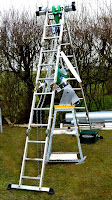
Lifting the assembled dome [14' or 4.3m Ø & 500lbs or 220kg] requires sufficient height and spacing for stepladders to manage the lift via a chain hoist. Clearance from the ladders is a problem. I have three, folding, builder's stepladders. So I can lash one in the middle. As an inverted V [or even a Pi shape] over two straightened ladders. To add considerably more room beneath the ladders. 

Handy for lifting the very bulky dome without hitting the undersides of the ladders. The stepladders have steady bars across their feet. Providing remarkable stability. The lifts will be of very limited height. So there is little danger of toppling. These stepladders are individually rated at 330lbs or 150kg. They are usually referred to as "multi-purpose" or "hinged ladders."

Lifting the [12] x 35kg, heavy [80lb] concrete foundation blocks into their excavated holes is very hard work. Until a length of timber is used as a lever over the back of the sack truck. Effortless antigravity at its best! With full control over pan and tilt. I just tried it and there is no need for a great length of 2x4 as a lever. 

I need several sheets of plywood for making arcs for the base ring template. So that I can place the foundation blocks accurately. The builder's merchants are closed to private customers due to the pandemic, lockdown restrictions. Though there is a "pay and collect" system available. The cost and difficulty of delivery to the door makes a collecting trip most likely. 

I am still waiting for the rain to end. So that I can mark and cut out the arcs outdoors. There is no room to handle full sheets of ply in the shed. I need to be able to swing a 2.1m radius bar to one side of the sheet.  

13.1.2021 A cold day with gales and wet, snow showers. The 2m long x 3T rating, round lifting slings have turned up a day later than promised by the website. These will be handy for getting the dome segments into the garden.


*

11.01.2021 Agricultural espionage?

 *

Monday, 41F, milder but yet more rain and even some wind. 

It is quite amazing how diligent online research can provide surprising detail and obscure information. YouTube is usually an encyclopaedic source if you can get past the glaringly obvious. 

Watching company promotional videos can plumb hidden depths you would never find in their carefully framed, sales brochure illustrations. The panning camera captures far more than was ever intended by the film maker. If only you know what to look for.

For example: The jointing method and internal reinforcement of seams between the segments of animal housings is laid bare. Without ever having to see the object first hand. Even if armed with a tape measure and LED torch. 

Capture a still from a slow motion replay and it can be processed to show infinitely more detail. Scale can be measured in image handling software without ever seeing the real thing. Lifelike images of enlarged objects, in colour to taste, can be set against photographed backgrounds. To be tentatively shared before the hideous "carbuncle" draws a partner's ire. 

This all helps to eliminate difficulties long before they arise. Or they can be studied and the process of adaptation can be set in motion. Long before the items are actually sitting on the lawn. Letting a problem lie quietly at the back of your mind will often lead to insights, reiteration and a problem solved. Make no hasty decisions. Only to repent at leisure. The design team [of one] has no room for costly wasters.

My long-winded rehearsals may well be seen as obsessive to some. If that is the case, then consider yourself extremely lucky. You must have the means at your disposal to overcome all obstacles. Simply by paying somebody else to worry about it and to overcome all hurdles. 

A solo attempt at anything places the onus on the perpetrator to get everything right, first time. The danger lies in grossly overestimating the design team's limited skills and knowledge! How can one possibly judge without testing them all in turn?


*


10.1.21

10.01.2021 Would a dome, by any other name, smell as sweet?

 *

You can blame the cold, wet and miserable, winter weather. For my recent flood of text and images. On the modification of a calf rearing, hemispherical shelter into a "proper" domed observatory. 

The rain and subsequent leaks, of my home made, plywood dome, has certainly driven me further down this path. Coating the damaged dome in GRP would have been expensive, dangerous of access, unsightly and probably, quite short-lived. 

Moreover I needed more room for my telescopes to swing. Even if I don't currently own "a Cat." [Catadioptric telescope.] The 7" f/12 has always been denied a dewshield due to severe, clearance problems. Nor can I get behind the eyepiece at low elevations due to the proximity of the plywood base ring. Trying to use the binoviewer "straight through" was an exercise in frustration. Made worse by the lack of inward focus if I added a star diagonal or solar wedge.

Borrowing the "off the shelf" hemispherical form of a calf igloo, as a donor shell, was always too obvious to miss. I had abandoned the idea earlier due to its much greater size and considerable weight. Leading to a horribly complicated and rather undernourished plywood, trapezoid observatory. Of attractive but decidedly, non-weatherproof form.  

The need for an entirely "one man band" construction effort has been slightly softened this time. I shall have a telescopic front loader place the completed dome on top of its building. Though the entire project is still rather daunting. Which is why I am rehearsing every detail in my mind and posting it here. Do not be offended if I say that this monologue is largely for my own benefit. Time and cost savings must be made by avoiding "unplanned idiocy."

Even acceptance of the basic "starter kit" is fraught with potential dangers and blunders. The parts are essentially simple but on a scale rarely attempted by a solo, septuagenarian DIY ATM-er. A farmer, or professional builder, would simply shrug off the difficulties and bring in more labour. Or hire a bigger machine. Machine access is poor and the pandemic means that employing a "carpenter's mate" is a complete non-starter. 

My wife is mostly supportive. Provided I don't erect a snow white monstrosity up there. There shall be no "White Elephant Observatories." Not in Her garden room!

Her latest addition to the list of potential names for said observatory made me smile:

"Stargrazer Observatory" is clever, apt, subtle, yet amusing in equal measure. I rather like this one.

There were some earlier, rather more obvious variations on: "Milky Way Observatory." Perhaps too obvious a connection to the young, bovine inhabitants being denied a potential home? 

Then there was "Taurus" The Bull constellation. A little too close to the derogatory term for "natural fertiliser" for my liking. 


*


9.01.2021 The devil is in the details.

 *

Saturday 9th Jan: I have been measuring up the existing observatory building for this slightly smaller dome. [Only 10cm smaller than the H&L] 

The Agritech Spheribox  has some advantages as a donor for an observatory dome over the Holm & Laue igloo. There would be no continuity problems in trying to avoid raised seams with shutter ribs. 

This image [Right] of a stack of [white] Spheribox segments seems to show a form of halving joint to left and right. Where the thinned edges overlap the lower segments. This provides a much smoother transition between panels. Rather than having a thick step at the lower edges where the three panels meet. 

I just wish I understood the orientation of the stack of panels. There seems to be drill holes along the nearest edge. Which should [in theory] be the lower edge where it rests on the ground. I found another image online of another stack but of inverted panels. The panels look identical to those shown here but this still makes no sense.

The Spheribox's large, semicircular doorway will be closed off. It weakens the hemispherical form and is usually reinforced with a curved band of galvanized steel on the edge of the open doorway. Which I obviously can't employ because it would block the view of the sky.

Fortunately the doorway's open area will be heavily reinforced by the structure around the observation slit and shutters. Only two, curved [3D] triangles will require closing off on either side of the slit. I might mould these area in GRP on a part of the dome. To achieve a neat, three dimensional, closing patch for either side.

These triangular patches are important for carrying the strength and stiffness of the dome form into the base ring below. There is spherical curvature in all directions. So flat plywood patches might jar the eye.
 
The "waste" material from the observation slit cut-out, from the central segment, would provide suitable [spherical] material. This could be bonded to provide neat triangles in the structure. Or I could laminate thin plywood to make curved, triangular patches. The image [left] shows a very rough drawing of a patch. Though not remotely to scale or even in the correct position.
 
Only the central area of the wide, arched doorway would become the lower part of the observation slit. With two, curved plywood ribs extending downwards to the sturdy base ring. Remember that the dome base will be resting on rollers. Which are, in turn, mounted on 1.5m [5'] high observatory walls. So the existing "doorway" would be completely unusable anyway.


I am [wildly] guessing that the lower edge of the GRP dome is thickened to resist wear from contact with the ground. If that is the case then the base ring can be raised slightly, within the dome skirt, to provide a decent, rainwater drip. I was worrying over this detail with the Holm & Laue dome and its base flange. Rainwater might have run between the GRP and the vulnerable, plywood base ring.
 
I have been checking for the availability of galvanized, 90° angle brackets [with pressed inbuilt stiffening ribs.] These would support the base ring mechanically on the inside of the dome skirt. I would pack up the dome on stands using the laser level on the skirt. This should ensure the base ring is perfectly level too.Though this can [and will] be double checked with the laser level, of course.
 
Fibreglass matt could be added on top of the ring. To provide a more solid bond between the base ring and the hemispherical GRP structure. Thereby adding considerable extra stiffness to the structure. Much like a bulkhead. This would also help to shed any interior condensation before it soaks into the plywood.
 
 
The Agritech Spheribox employs two, lifting brackets. On top, but widely spaced to lie over the segment seams. These seams must provide increased local strength. So I must reinforce the weakened area of the structure where I cut out the wide, observation slit. Width yet to be decided. I am not a fan of wide slits. The recommendation of 1/3 the diameter of the dome just looks wrong to my eyes. I did some experimenting with this on the plywood dome and ended up with a narrower slit. Which has not proved a problem with my refractors and manual dome rotation.
 
The wide separation of the lifting brackets offers the opportunity to fit a strong, metal, spacing bar between the lifting points. The danger is that lateral, crushing forces would be trying to close the open slit area, during a lift. This must be safely resisted where the slit denies the central panel its full, design strength. The bridging bar could also become a handy, anchor point for internal hoists. Which I use for exchanging long and heavy OTAs on the mounting in my present dome. 

 
*


9.1.21

7.01.2020 Any colour you like as long as it's green?

 *

Thursday 7th overcast as the thin snow melts.

I have previously mentioned my wife's dislike for white domes dominating the garden skyline. Which raised the possibility of "local resistance." White is traditional. It reflects the sun's heat and maintains a more even temperature. Or does it? See below.

At which point a green dome raised its head during an image search. Which was duly spotted and remarked upon in positive terms by my wife.

I can certainly see what the good lady means about white domes. The plywood dome was lightly covered in snow at the weekend. Which made it stand out like a sore thumb from the road at 200 meters and well beyond. 

It screams "LOOK AT ME!!!" from afar. Particularly against its dark background! Though, fortunately, a tall hedge and a barn lie in the foreground. Helping to hide the rather unexpected shape in the landscape at certain viewing angles.

Agritech.Srl have been making fibreglass silos in Italy since the mid-80s. Their range of GRP animal shelters includes the dome-shaped Spheribox shown here. An ideal observatory, dome donor?

The claimed dimension are 4.3m Ø x 2.18m high [14' 1" Ø x 7' 2" high] and weighing 220kg for the bare GRP "dome." Three, horizontal segments make up the hemisphere. With bolted together, overlaps on the upper segment providing weather protection from rain run-off. 

No raised, exterior flanges, nor seams. Which gives a smoother appearance than the Holm & Laue. The horizontal segmented, surface texture is considered rather attractive by those who matter. Because it helps to break up the otherwise, uniformly smooth surface. Providing a whole range of colour shades from its multiple reflections with the sky and surrounding trees. See the stock, Agritech images here.

Making it far more "stealthy" when seen from a distance. As is my present dome with its trapezoid panels tilted at various angles to the sky. Though in this case the sage green paint is now largely matt. The temperature of sun facing, plywood surfaces literally soars! 

Agritech also do a white finish, domed calf shelter. For anyone who prefers this [modern?] traditional colour. Both colours are claimed to be strongly solar reflecting. To protect the housed animals from overheating in hot sunshine during heatwaves. Everyday experience suggests that the white finish would reflect more heat. Though this will depend entirely on the absorption coefficient at the frequency of the incoming, thermal radiation. 

The same applies, of course, with heat radiating from the dome's surface. Which leaves one wondering about the thermal qualities of wood lined, antique observatories with sheet copper roofs. Perhaps this is where the significance of "dome seeing" became established?


*

5.1.21

5.01.2021 Fetch?

 *

Tuesday 5th Jan. I have been trying to get my head around the sheer size of the new dome components.

The H&L importer has informed me that I'll need a telescopic front loader to remove the dome segments from the German delivery lorry. They are assuming that all buyers are agricultural businesses and suitably equipped. So now I am probably going to need my car trailer. To get the three segments home from the drop-off point at a local farm. With this in mind I set out some handy lengths of batten on top of the trailer sides for true scale.

The three dome segments flare from 1.46m wide at the curved "doorway" to 2.3m maximum [curved] width. Then taper down to a point at 3.9m long overall. Though the completed dome is 4.4 meters wide the doorway shortens the footprint in the for and aft sense. Imagine it as a straight, vertical slice chopped off the hemisphere.

My trailer measures roughly 1.3m x 2m. So the segments would drape nicely over the top of the trailer on all sides. I'd hoped they would fit inside at the front but this is impossible. So they would have to overlap by about a meter front and back.

A couple of 2x4s laid across the trailer would provide support in the middle of the segments. Location and support blocks inside the trailer sides would keep them in place. This will also help to avoid the tail end points dragging along the road. The whole lot would be well secured to the trailer with multiple ratchet straps. 

The trailer's official load capacity exceeds the weight of the dome components by nearly 100%. So no problem there. Provided I distribute the load properly into the trailer base. Without an example of a segment available it becomes pure guesswork. 

Perhaps the segments should stand on edge as they do in the loaded lorry picture above? Though they would then project much further to the rear. Fortunately the "bent leaf" shape has most of its mass well to the front. Where it is obviously widest. 

The horse boxes available for hire at the petrol stations would house the segments on edge. Or a hired, car transporter trailer would also work and be easier to unload. I have just checked the trailer website and it seems they use a 13pin plug. My car does not have such a plug. It has far fewer pins. [7] Oh, dear. Plan B is definitely off the table.

It has occurred to me that I should make the new building's [4.4m Ø] top ring slightly higher than the old 3.2m Ø one. That way I can lay the new ring over the old timber without interfering with dome movement. Nor needing to dismantle any of the older building's timbers. Nor touch the plywood dome until much later. The existing, top [roller] ring can even be used to temporarily support the new, larger ring in suitable places using scraps of plywood or batten.


*

2.1.21

2.01.2021 Sorcerer's apprentice!

 *

Saturday 2nd January 2021, overcast and misty start cleared to brief spells of sunshine. 

Talking of spells: I had to remove 35 litres of rainwater from the collection trays on the dome base ring today. That's about 7 gallons in Olde Money. The magic broom was still hungover from New Year. So my spells didn't work on that. 

It was back to manual labour. Up and down the stepladder, carrying a nearly full bucket, four times. Now I feel just like a cartoon character. I just wish it was a stronger one. A superhero would do nicely. I should have rigged up a large funnel and hose out to the surrounding ground by now. Perhaps I need the physical exercise more than the mental variety?

Meanwhile, I have been exercising my mind on construction and expansion of the building. By using full height 4m lengths of timber I can quickly establish the height and spacing. 50x100 doubled is easier to handle than 100x100 sawn timber. Diagonal bracing is optional if the cladding plywood is used as stressed skin. 

The cladding is grooved ply and each sheet will provide 2 full lengths. This will only reach the observatory floor level. The extra height demands sheets be cut down to match the required height. Leaving a [potentially exposed]  horizontal joint in the cladding at roughly 3/4 height of the building.

The next decision is whether to build panels for more rapid construction. Rather than adding the cladding sheets to the completed, but bare skeleton. 

Panels would be heavy and long [4m tall] but greatly reduce the need to clamber all over the building. By ladder, to add the necessary, hundreds of fixing screws. With the risk of slippage and geometric inaccuracy when fitting the cladding sheets. A dihedral angle [mitre] would be required on the vertical posts at vertical panel junctions. Easily managed with the table saw.

I wasted hundreds of hours individually cutting mitres on every piece of timber in the last, building skeleton. I was having to compensate for twist, spacing and bending of the 4x4 uprights and the heavy timber being used for cross bracing. Often needing several cuts to get a perfect joint. 

Meaning a return to the ground to make the saw cut. Then back up to check the fit and angle. Repeated, several times, for every single mitre, it all added up to a huge amount of wasted time. 

Vertical panels would all be identical units and have all square joints. The tops could be lifted into place with a pulley or winch after the bottoms were pushed against the building. The foundation blocks would all have to be perfectly spaced and not disturbed during fitting. The upright tops would be clamped at the underside of the top ring before fixing. 

Panel design is variable within the fixed size format. Diagonal bracing and only 50mm thick? Rather than 100mm deep with the uprights framing the edge? A horizontal batten would be required at the joint between cladding sheets for edge support.

Reaching the entire circumference of the building with full panels would be very difficult if they were heavy. At least 12m of 2x4 plus cladding. I'm not superman. Though safe access at obs. floor level would be possible from the existing building. The panels could be walked around.

However tempting to go with panels, I'm seeing repeated heavy lifting at every stage. 

Assume pairs of 2x4 uprights, Each post lifted, fitted and then clamped together individually. Rest on the ground bracket and then a tack screw to a 2 layer top ring. Brace the uprights afterwards. Because there is no really need for structural strength until the dome is fitted. 

A distortion free and self supporting, external shell is all that is required. I am only enlarging the footprint at this stage. Beef up the top ring with more layers of plywood once it is supported by all the uprights. This will avoid having to raise the huge and still flexible top ring in one go. Which was extremely difficult even at 3m diameter on the last build. I can carry smaller arcs up and clamp and screw them.


*